JL2-F140-M LED Sensor Controller Communication Driver is the driver to communicate with LED Sensor lighting controler of JoongAng Control Co., Ltd. in Korea.
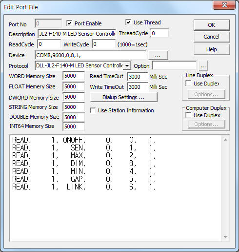
<Figure 1> is read setting example of JL2-F140-M LED Sensor Controller communication driver.
|
|
| <Figure 1> Read setting example of JL2-F140-M LED Sensor Controller communication driver |
Device part of <Figure 1> input Com Port(COM8), Baud Rate(9600), Parity Bit(0), Data Bit(8), Stop Bit(1) respectively.
JL2-F140-M LED Sensor Controller communication driver’s read schedule
Read schedule setting parameters are as follows:
1) STATION – 0 ~ 255 controler ID.
2) Read command – Command = ONOFF, SEN, MAX, DIM, MIN, GAP, LINK.(Refer to <Table 1>)
3) Read Start Address – Don't care.
4) Save Start Address for Communication Server – Saving start address of Communication Server.
5) Read Size – Size = Fix to 1.
Read schedule example)
READ, 1, ONOFF, 0, 0, 1,
READ, 1, SEN, 0, 1, 1,
READ, 1, MAX, 0, 2, 1,
READ, 1, DIM, 0, 3, 1,
READ, 1, MIN, 0, 4, 1,
READ, 1, GAP, 0, 5, 1,
READ, 1, LINK, 0, 6, 1,
<Table 1> is a description of read command and stored values of JL2-F140-M LED Sensor Controller communication driver.
| Read Command | Contents | Stored Values | Remarks |
| ONOFF | Read of sensor operation On/Off status | Start Add + 0 : On/Off status | 0 = Off, 1 = On |
| SEN | Read of sensor sensitivity level | Start Add + 0 : sensor sensitivity level | 0 ~ 15, 0 = Off |
| MAX | Read of max bright value | Start Add + 0 : max bright value | 1 ~ 10 = 10% ~ 100% |
| DIM | Read of dimming speed | Start Add + 0 : dimming speed |
1 ~ 255 mSec |
| MIN | Read of min bright value | Start Add + 0 : min bright value | 0 ~ 10 = 0%(Off) ~ 100% |
| GAP | Read of gap control setting/clear status | Start Add + 0 : setting/clear status | 0 =clear, 1 = setting |
| LINK | Number of interlocking controller | Start Add + 0 : number of interlocking controller | 1 ~ 32 |
| <Table 1> Read commands type and stored values of JL2-F140-M LED Sensor Controller communication driver | |||
JL2-F140-M LED Sensor Controller communication driver store the same data in WORD, DWORD, FLOAT memory, but the data formats are different.
If you click the icon
![]() in protocol option part, you can see the dialogue
box such as <Figure 2>. you can also set read schedule by using this part.
in protocol option part, you can see the dialogue
box such as <Figure 2>. you can also set read schedule by using this part.
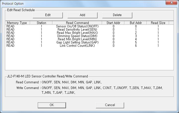 |
| <Figure 2> Example of JL2-F140-M LED Sensor Controller communication driver’s Option dialogue box |
You can also set read schedule by using
![]() ,
,
![]() ,
,
![]() button and listbox of <Figure 2>.
button and listbox of <Figure 2>.
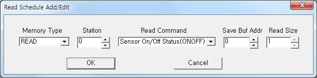 |
| <Figure 3> Example of JL2-F140-M LED Sensor Controller communication driver’s read schedule Add/Edit dialogue box |
When you click Add button or Edit button in dialogue box of <Figure 2>, dialogue box of <Figure 3> will be shown.
You can set LED sensor controller by using write commands.
Bit write
Bit write and word write have the same setting parameters except output value(0 or 1).
Word write
Word write setting parameters are as follows:
1) PORT : Port no. (0 ~ 255)
2) STATION : 0 ~ 255 controler ID.
3) ADDRESS : Don't care.
4) EXTRA 1 : Write Command = ONOFF, SEN, MAX, DIM, MIN, GAP, LINK, CONT, T_ONOFF, T_SEN, T_MAX, T_DIM, T_MIN, T_GAP, T_LINK. (Refer to <Table 2>)
5) EXTRA 2 : CONT write comand = Number of interlocking controller,
T_ONOFF, T_SEN, T_MAX, T_DIM, T_MIN, T_LINK write command = Number of total controller,
Other write command = Don't care.
<Table 2> is a description of write command and write value of JL2-F140-M LED Sensor Controller communication driver.
| Write Command | Contents | Output value(range) | Extra2 |
| ONOFF | Write of sensor operation status(On/Off) | 0 = Off, 1 = On | Don't care |
| SEN | Write of sensor sensitivity level | 0 ~ 15, 0 = Off | |
| MAX | Write of max bright value | 1 ~ 10 = 10% ~ 100% | |
| DIM | Write of dimming speed | 1 ~ 255 mSec | |
| MIN | Write of min bright value | 0 ~ 10 = 0%(Off) ~ 100% | |
| GAP | Write of gap control setting/clear status | 0 =clear, 1 = setting | |
| LINK | Number of interlocking controller writeing | 1 ~ 32 | |
| CONT | Write of interlocking controller number when sensor sensing | Don't care | Number of interlocking controller |
| T_ONOFF | Write of multi sensor operation status(On/Off) | 0 = Off, 1 = On | Number of total controller |
| T_SEN | Write of multi sensor sensitivity level | 0 ~ 15, 0 = Off | |
| T_MAX | Write of multi max bright value | 1 ~ 10 = 10% ~ 100% | |
| T_DIM | Write of multi dimming speed | 1 ~ 255 mSec | |
| T_MIN | Write of multi min bright value | 0 ~ 10 = 0%(Off) ~ 100% | |
| T_GAP | Write of multi gap control setting/clear status | 0 =clear, 1 = setting | Don't care |
| T_LINK | Number of multi interlocking controller writeing | 1 ~ 32개 | Number of total controller |
| <Table 2> write command and write value of JL2-F140-M LED Sensor Controller communication driver | |||
Write example 1)
PORT:0, station:1, ADDRESS:0000, Extra1:ONOFF, Extra2 : 0
The setting parameter shown above is an example of write for sensor operation status(On/Off) setting of JL2-F140-M LED Sensor Controller connected with 0 port and 1 controller ID.
Write example 2)
PORT:0, station:1, ADDRESS:0000, Extra1:MAX, Extra2 : 0
The setting parameter shown above is an example of write for max bright value setting of JL2-F140-M LED Sensor Controller connected with 0 port and 1 controller ID.
Write example 3)
PORT:0, station:0, ADDRESS:0003, Extra1:MIN, Extra2 : 0
The setting parameter shown above is an example of write for min bright value setting of JL2-F140-M LED Sensor Controller connected with 0 port and 1 controller ID.
Block write
JL2-F140-M LED Sensor Controller communication driver don’t support ‘Block write’.
<Figure 4> shows the appearance of JL2-F140-M LED Sensor Controller.
 |
| <Figure 4> Appearance of JL2-F140-M LED Sensor Controller |