JC-2302 Lighting Controller Communication Driver is the driver to communicate with JC-2302 or JC-2303 of JoongAng Control CO., LTD. in Korea.
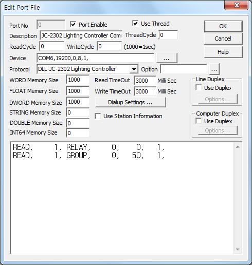
<Figure 1> is read setting example of JC-2302 Lighting Controller communication driver .
|
|
| <Figure 1> Read setting example of JC-2302 Lighting Controller communication driver |
Device Setting of <Figure 1> are input, Com Port(COM6), Com Speed(19200), Parity Bit(0), Data Bit(8), Stop Bit(1).
Also, you can set controller model(0 = 2302, 1 = 2303, default : 0) by usng 'Option' part.
JC-2302 Lighting Controller communication driver read schedule
Read schedule setting parameters are as follows:
1) STATION – Desdination Address = 1 ~ 250.
2) Read Command – Command = RELAY, DIM, GROUP, PATTERN, SCENE, EVENT, POWER, SMART, VOLT, CURR, ENERGY. (Refer to <Table 1>)
3) Read Start Address – don't care.
4) Save Start Address for Communication Server – saveing start address of Communication Server.
5) Read Size – read size = 1.
Read schedule example)
READ, 1, RELAY, 0, 0, 1,
READ, 1, GROUP, 0, 50, 1,
<Table 1> is a description of read commands type and stored values of JC-2302 Lighting Controller communication driver.
| Read Command | Content | Store Values | Remarks |
RELAY |
Read of Relay Status |
Start Add + 0 : 0 ~ 9 bit R1 ~ R10
ON/OFF Relay Status, Start Add + 1 ~ 24 : 0 ~ 9 bit R11 ~ R250 ON/OFF Relay Status, Start Add + 25 : 0 ~ 5 bit R251 ~ R256 ON/OFF Relay Status |
|
| DIM | Read of Dimmer Status | Start Add + 0 ~ 63 : Dimmer 1 ~ 64 Current Value | Value = 0 ~ 100 |
GROUP |
Read of Group Status |
Start Add + 0 : 0 ~ 9 bit G1 ~ G10
ON/OFF Group Status, Start Add + 1 ~ 24 : 0 ~ 9 bit G11 ~ G250 ON/OFF Group Status, Start Add + 25 : 0 ~ 4 bit G251 ~ G255 ON/OFF Group Status |
|
PATTERN |
Read of Pattern Status |
Start Add + 0 : 0 ~ 9 bit P1 ~ P10
ON/OFF Pattern Status, Start Add + 1 ~ 24 : 0 ~ 9 bit P11 ~ P250 ON/OFF Pattern Status, Start Add + 25 : 0 ~ 4 bit P251 ~ P255 ON/OFF Pattern Status |
|
SCENE |
Read of Scene Status |
Start Add + 0 : 0 ~ 9 bit S1 ~ S10
ON/OFF Scene Status, Start Add + 1 ~ 24 : 0 ~ 9 bit S11 ~ S250 ON/OFF Scene Status, Start Add + 25 : 0 ~ 4 bit S251 ~ S255 ON/OFF Scene Status |
|
EVENT |
Read of Event Status |
Start Add + 0 : 0 ~ 9 bit E1 ~ E10
ON/OFF Event Status, Start Add + 1 ~ 24 : 0 ~ 9 bit E11 ~ E250 ON/OFF Event Status, Start Add + 25 : 0 ~ 4 bit E251 ~ E255 ON/OFF Event Status |
|
| POWER | Read of Power Detect | Start Add + 0 : Power Detect Status | 255 = blackout, 0 = restoration |
SMART |
Read of Smart Relay Status |
Start Add + 0 : 0 ~ 9 bit SR1 ~
SR10 ON/OFF Smart Relay Status, Start Add + 1 ~ 24 : 0 ~ 9 bit SR11 ~ SR250 ON/OFF Smart Relay Status, Start Add + 25 : 0 ~ 5 bit SR251 ~ SR256 ON/OFF Smart Relay Status |
|
| VOLT | Read of Voltage | Start Add + 0 ~ 255 : Voltage 1 ~ 256 Value | Word unit |
| CURR | Read of Current | Start Add + 0 ~ 255 : Current 1 ~ 256 Value | Word unit |
| ENERGY | Read of Electric Energy | Start Add + 0 ~ 255 : Energy 1 ~ 256 Value | Double Word unit |
| PHOTO | Read of Photo Sensor Status | Start Add + 0 ~ 63 : Photo Sensor 0 ~ 63 Value | Word unit |
| WATT | Read of Electric Watt | Start Add + 0 ~ 255 : Electric Watt 1 ~ 256 Value | Double Word unit, for 2303 model |
| MOTION | Read of Motion Sensor Enable | Start Add + 0 ~ 63 : Motion Sensor Enable 1 ~ 64 Value | 255 = On, 0 = Off |
| <Table 1> Read commands type and stored values of JC-2302 Lighting Controller Communication Driver | |||
If you click the icon
![]() in
protocol option part, you can see the dialogue box such as <Figure 2>. you can
also set read schedule by using this part.
in
protocol option part, you can see the dialogue box such as <Figure 2>. you can
also set read schedule by using this part.
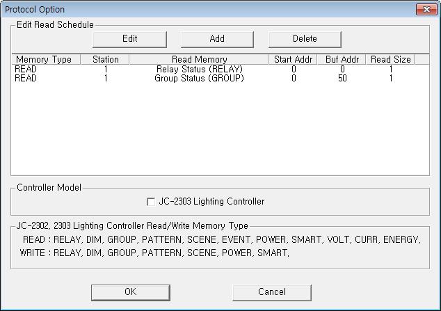 |
| <Figure 2> Example of JC-2302 Lighting Controller Communication Driver’s Option dialogue box |
You can set read schedule by using
![]() ,
,
![]() ,
,
![]() button and listbox of <Figure 2>.
button and listbox of <Figure 2>.
Also, you can set controller model the part of 'Controller Model' of <Figure 2>.
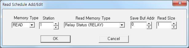 |
| <Figure 3> Example of JC-2302 Lighting Controller communication driver’s read schedule Add/Edit dialogue box |
When you click Add button or Edit button in dialogue box of <Figure 2>, dialogue box of <Figure 3> is shown.
You can control the Relay, Group, etc values of JC-2302 by using write commands.
Bit write
Bit write setting parameters are as follows:
1) PORT : Port no. (0 ~ 255)
2) STATION : Desdination Address = 1 ~ 250.
3) ADDRESS : Address of Relay, Group, Pattern, Pattern, etc. (10 digit). range = 0 ~ 255 or 0 ~ 512(for JC-2303 RELAY command). (refer to <Table 2>)
4) EXTRA 1 : Write Command = RELAY, DIM, GROUP, PATTERN, SCENE, EVENT, POWER, SMART.
5) EXTRA 2 : don't care.
Write example 1)
PORT:0, station:1, ADDRESS:0000, Extra1:RELAY, Extra : 0
The setting parameter shown above is an example of bit write for control(ON/OFF) R1 Relay of JC-2302 Controller connected with 0 port, set to 1 Destination Address.
Write example 2)
PORT:0, station:1, ADDRESS:0005, Extra1:RELAY, Extra : 0
The setting parameter shown above is an example of bit write for control(ON/OFF) R6 Relay of JC-2302 Controller connected with 0 port, set to 1 Destination Address.
Write example 3)
PORT:0, station:1, ADDRESS:0014, Extra1:GROUP, Extra : 0
The setting parameter shown above is an example of bit write for control(ON/OFF) G15 Group Relay of JC-2302 Controller connected with 0 port, set to 1 Destination Address.
<Table 2> is a description of write commands and range of the write value for JC-2302 Lighting Controller communication driver.
| Write Command | Content | Range of ADDRESS | Range of Write Value |
| RELAY | Relay control | 0 ~ 255 = R1 ~ R256 for 2302 model 0 ~ 255 = R1 ~ R256 for 2303 model |
1 = ON, 0 = OFF |
| DIM | Write of Dimmer value | 0 ~ 63 | 0 ~ 100, (100 = ON, 0 = OFF) |
| GROUP | Group Relay control | 0 ~ 254 = G1 ~ G255 | 1 = ON, 0 = OFF |
| PATTERN | Pattern control | 0 ~ 254 = P1 ~ P255 | 1 = ON, 0 = OFF |
| SCENE | Write of Scene | 0 ~ 254 = S1 ~ S255 | 1 = ON, 0 = OFF |
| POWER | Power Detect control | don't care | 1 = blackout, 0 = restoration |
| SMART | Smart Relay control | 0 ~ 255 = SR1 ~ SR256 | 1 = ON, 0 = OFF |
| <Table 2> Write commands and range of the write value for JC-2302 Lighting Controller communication driver | |||
Word Write
Word write and bit write have the same setting parameters except output value.
Block Write
Block write use PlcScanWriteBlock script such as follows.
script function and parameters : @PlcScanWriteBlock(int port, int station, int address, string extra1, string extra2, object array_value, int array_size);
Example of script 1 ( MOTION block write )
ushort Val[64];
Val[0] = 255;
Val[1] = 0;
Val[2] = 0;
Val[3] = 0;
Val[4] = 255;
Val[5] = 255;
Val[6] = 255;
Val[7] = 0;
Val[8] = 255;
Val[9] = 255;
...
@PlcScanWriteBlock(0, 0, 0, "MOTION", 0,
Val, 64);
You have to connect serial communication cable in the following ways.
Connection of RS-485 communication cable
You can connect RS-485 communication cable to terminal '+MAIN-' ( left = +, right = - ) of JC-2302 Controlleror and PC Respectively.
<Figure 4> shows the appearance of JC-2302 Lighting Controller.
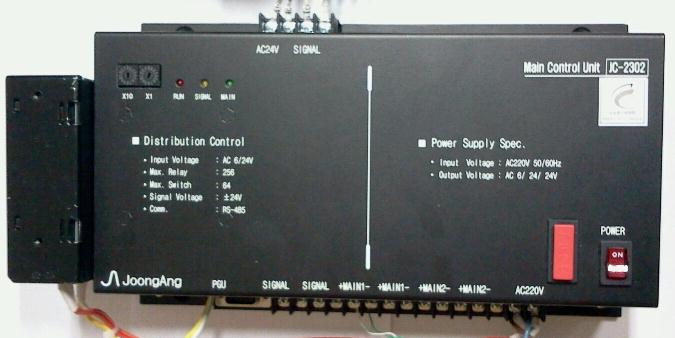 |
| <Figure 4> Appearance of JC-2302 Lighting Controller |