HNS Smart I/O I Read/Write communication driver is the driver to communicate with Smart I GPIO equipment of HNS Co., Ltd. in Korea.
Note) HNS Smart I/O I Read/Write communication driver use only Smart profram(CE OS).
HNS Smart I/O I Read/Write communication driver support by using DLL driver of 'HNS'. So, it needed the DLL file provided by 'HNS'.
Needed DLL filename : IEC1000HWCON.dll
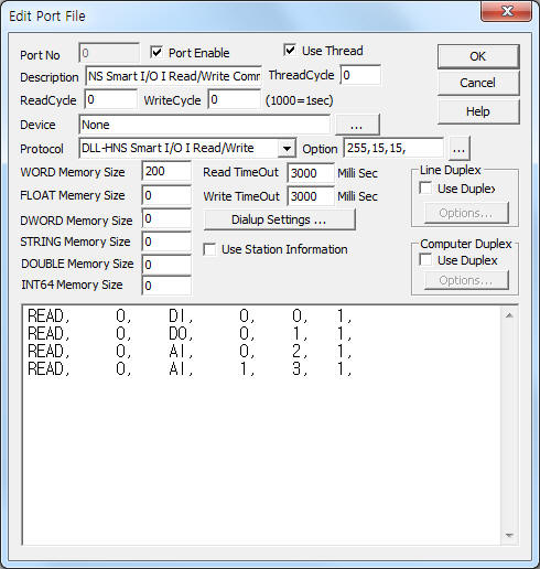
<Figure 1> is read setting example of HNS Smart I/O I Read/Write communication driver.
|
|
| <Figure 1> Read setting example of HNS Smart I/O I Read/Write communication driver |
Please input 'None' at Device part.
In protocol option part, you can set the following: selection of input or output for Digital Input module(0 ~ 255, 0 = All input, 255 = all output, default = 0), selection of input or output for FET output module(0 ~ 15, 0 = All input, 15 = all output, default = 15), selection of input or output for Relay S/W output module(0 ~ 15, 0 = All input, 15 = all output, default = 15). Each argument is a comma-delimited.
HNS Smart I/O I Read/Write communication driver read schedule
Read schedule setting parameters are as follows:
1) Station – Don't care.
2) Read command – Command = DI, DO, AI. ( refer to <Table 1> )
3) Read start address – Don't care.
4) Save start address for Communication Server – Saving start address of Communication Server.
5) Read Size – Fixed to 1.
Read schedule example)
READ, 0, DI, 0, 0, 1,
READ, 0, DO, 0, 1, 1,
READ, 0, AI, 0, 2, 1,
READ, 0, AI, 1, 3, 1,
<Table 1> is data saving address and contnets for each read command.
| Read command | Contents | Data saving address |
Range |
| DI | Read of 8 channel status of digital input module | Start addr + 0 : 0 ~ 7 bit DI On/Off status | 0 : Off, 1 : On |
| DO | Read of 8 channel FET, Relay S/W output module | Start addr + 0 : 0 ~ 3 bit FET output On/Off status Start addr + 0 : 4 ~ 7 bit Relay output On/Off status |
|
| AI | Read of A/D(analog input) module | Start addr + 0 : 0 ~ 4095( 12 bit ) analog status | 0 ~ 4095 |
| <Table 1> Data saving address and contnets for each read command | |||
HNS Smart I/O I Read/Write store the same data in WORD, DWORD, FLOAT, DOUBLE, INT64 memory, but the data format are different.
If you click the icon ![]() in protocol option part at
<Figure 1>, you
can see the dialogue box such as <Figure 2>. you can also set read schedule by
using this part.
in protocol option part at
<Figure 1>, you
can see the dialogue box such as <Figure 2>. you can also set read schedule by
using this part.
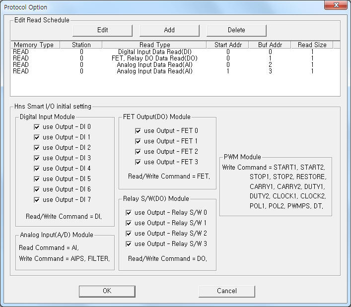 |
| <Figure 2> Example of HNS Smart I/O I Read/Write communication driver’s Option dialog box |
You can set read schedule by using ![]() ,
, ![]() ,
, ![]() button and listbox of <Figure
2>.
button and listbox of <Figure
2>.
Also, you can set 'selection of input or output for Digital Input module', 'selection of input or output for FET output module', 'selection of input or output for Relay S/W output module' by using the part of 'Digital Input Module', 'FET Output Module', 'Relay S/W Module' of <Figire 2>.
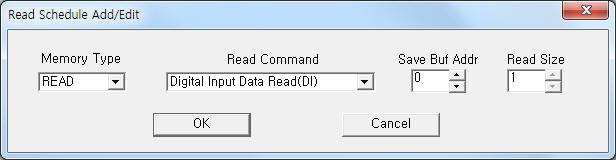 |
| <Figure 3> Example of HNS Smart I/O I Read/Write communication driver’s read schedule Add/Edit dialog box |
When you click Add button or Edit button in dialogue box of <Figure 2>, dialogue box of <Figure 3> is shown.
You can control HNS Smart I/O I module by using 'writing settings'.
Digital Write
Digital write and analog write have the same setting parameters except output value.
Analog Write
Analog write setting parameters are as follows:
1) PORT Port no. (0 ~ 255)
2) STATION Don't care.
3) ADDRESS Point address for writing or data saving address. ( decimal unit )
DI, DO write command = 0 ~ 7 point address.
etc write command(except RESTORE) = data saving address.
4) Extra1 Write command = DI, DO, AIPS, FILTER, START1, START2, STOP1, STOP2, RESTORE, CARRY1, CARRY2, DUTY1, DUTY2, CLOCK1, CLOCK2, POL1, POL2, PWMPS, DT.
DI, DO = control setting of digital input, FET/Relay output.
AIPS = setting of Pre Scale value for analog input module.
FILTER = Filtering Enable(On), Disable(Off) setting of analog input module.
START1, START2 = Start command for PWM module 1, 2. After writing, the 'output value' save at 'Address' memory.
STOP1, STOP2 = Stop command gor PWM module 1, 2. After writing, the 'output value' save at 'Address' memory.
RESTORE = Restore command for PWM module.
CARRY1, CARRY2 = Carry Counter setting for PWM module 1, 2. After writing, the 'output value' save at 'Address' memory.
DUTY1, DUTY2 = Duty rate setting for PWM module 1, 2. After writing, the 'output value' save at 'Address' memory.
CLOCK1, CLOCK2 = Clock Devider setting for PWM module 1, 2. After writing, the 'output value' save at 'Address' memory.
POL1, POL2 = Polarity Set Enable(On), Disable(Off) setting for PWM module 1, 2. After writing, the 'output value' save at 'Address' memory.
PWMPS = Pre Scale setting for PWM module. After writing, the 'output value' save at 'Address' memory.
DT = Dead Time setting for PWM module. After writing, the 'output value' save at 'Address' memory.
5) Extra2 Don't care.
Write example 1)
PORT:0, station:0, ADDRESS:0000, Extra1: DO, Extra2 : 0
The setting parameter shown above is a control(On, Off) example for 1st FET output.
Write example 2)
PORT:0, station:0, ADDRESS:0002, Extra1: DO, Extra2 : 0
The setting parameter shown above is a control(On, Off) example for 3rd FET output.
Write example 3)
PORT:0, station:0, ADDRESS:0007, Extra1: DO, Extra2 : 0
The setting parameter shown above is a control(On, Off) example for 4th Relay S/W output.
Write example 4)
PORT:0, station:0, ADDRESS:0100, Extra1: DUTY1, Extra2 : 0
The setting parameter shown above is Duty rate setting example of PWM module 1
After writing, the setting 'Duty rate' value save at 100 address WORD, DWORD, FLOAT, DOUBLE, INT64.
<Figure 4> is appearance of HNS Smart I/O I Read/Writ equipment.
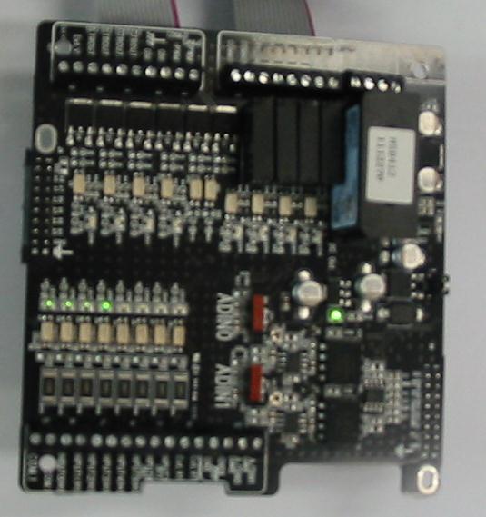 |
| <Figure 4> Appearance of HNS Smart I/O I Read/Writ equipment |