Hando USB IO Module communication driver is the driver to communicate with USB IO Module of Hando Computer Co., Ltd. in Korea.
Note) Hando USB IO Module communication driver must not use 'Thread' option.(when you using 'thread' option, the 'Communication Server' program will be down)
You can set USB board ID and type of Input, Output by using 'uiomodule.exe' provided by Hando USB IO Module.
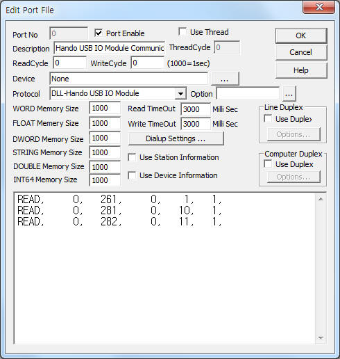
<Figure 1> is read setting example of Hando USB IO Module communication driver.
|
|
| <Figure 1> Read setting example of Hando USB IO Module communication driver |
Please input 'None' at Device part of <Figure 1>.
Hando USB IO Module communication driver read schedule
Read schedule setting parameters are as follows:
1) Station – don't care.
2) Read USB board ID – board ID = 261 ~ 269, 281 ~ 287, 289. ( refer to <Table 1> )
3) Read start address – don't care.
4) Save start address for Communication Server – Saving start address of Communication Server.
5) Read Size – fixed to 1.
Read schedule example)
READ, 0, 261, 0, 1, 1,
READ, 0, 281, 0, 10, 1,
READ, 0, 282, 0, 11, 1,
<Table 1> is data saving address and contents of Hando USB IO Module communication driver.
| USB board ID | Contents | Data saving address |
Rnage |
| 261 ~ 269 | Read of input value for 260 module | Start Addr + 0 : 0 ~ 7 DI bit On/Off status (according setting) |
0 : On, 1 : Off reverse On/Off |
| 281 ~ 287, 289 | Read of input value for 280 module | ||
| <표 1> Data saving address and contents of Hando USB IO Module communication driver | |||
Hando USB IO Module communication driver store the same data in WORD, DWORD, FLOAT, DOUBLE, INT64 memory, but the data format are different.
If you click the icon
![]() in protocol option part, you can see the dialog
box such as <Figure 2>. you can also set read schedule by using this part.
in protocol option part, you can see the dialog
box such as <Figure 2>. you can also set read schedule by using this part.
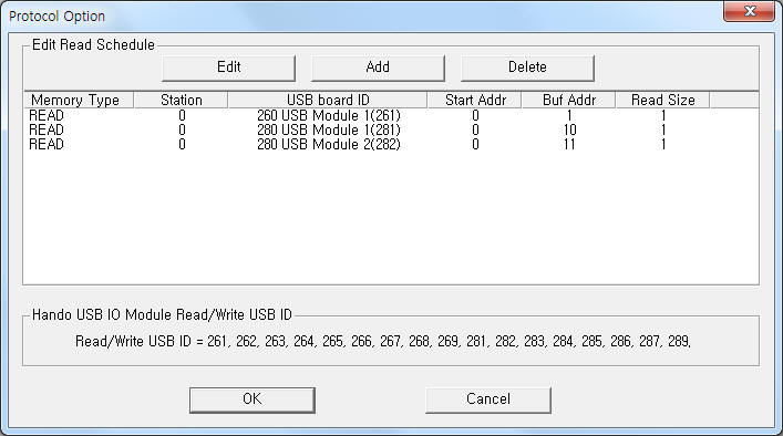 |
| <Figure 2> Example of Hando USB IO Module communication driver’s protocol option dialog box |
You can set read schedule by using
![]() ,
,
![]() ,
,
![]() button and listbox of <Figure 2>.
button and listbox of <Figure 2>.
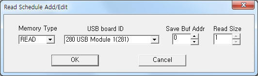 |
| <Figure 3> Example of Hando USB IO Module communication driver’s read schedule Add/Edit dialog box |
When you click Add button or Edit button in dialog box of <Figure 2>, dialog box of <Figure 3> will be shown.
You can set Hando USB IO Module by using 'writing settings'.
Digital Write
Digital write and analog write have the same setting parameters except output value and address.
Analog Write
Analog write setting parameters are as follows:
1) PORT Port no. (0 ~ 255)
2) STATION don't care.
3) ADDRESS 1 ~ 8 output address.(according to setting)
4) Extra1 board ID = 261 ~ 269, 281 ~ 287, 289. ( refer to <Table 1> )
5) Extra2 selection of blink option.
0 = don't use,
1 ~ 15 = On/Off Blink : 0.2second x value of Extra2,
16(10h) ~ 255(FFh) = 0.2second x higher 4 bit of Extra2(1 ~ 15) : On, 0.2second x lower 4 bit of Extra2(1 ~ 15) : Off.
Write example 1)
PORT:0, station:0, ADDRESS:0001, Extra1:281, Extra2 : 0
The setting parameter shown above is On/Off control example of 1 USB IO for 281 module.
Write example 2)
PORT:0, station:0, ADDRESS:0002, Extra1:281, Extra2 : 10, Output Value = 1,
The setting parameter shown above is 2 second period On/Off Blink control example of 2 USB IO for 281 module.
Write example 3)
PORT:0, station:0, ADDRESS:0003, Extra1:281, Extra2 : 82, Output Value = 1,
The setting parameter shown above is 1 second On, 0.4 second Off period Blink control example of 3 USB IO for 281 module. (82 = 52h)
<Figure 4> is appearance of Hando USB IO Module.
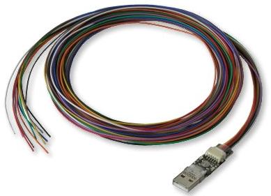 |
| <Figure 4> Appearance of Hando USB IO Module(280 module) |