Genius GT-600 communication driver is the driver to communicate with Smart Exhaust Throttle Valve controller of Genius Technologies Co., Ltd. in Korea.
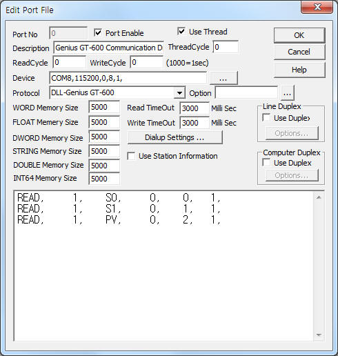
<Figure 1> is read setting example of Genius GT-600 communication driver.
|
|
| <Figure 1> Read setting example of Genius GT-600 communication driver |
Device part of <Figure 1> input Com Port(COM1), Baud Rate(115200), Parity Bit(0), Data Bit(8), Stop Bit(1) respectively according to setting of controller.
Genius GT-600 communication driver read schedule
Read schedule setting parameters are as follows:
1) STATION – Don't care.
2) Read command – Command = S0~S4, PV, VP, ASS, P1~P2, SP, I0~I5, VT, AR, T0~T5, SR, SU, SS, SV, XM, X0~X4, M0~M4. ( Refer to <Table 1> )
3) Read start address – Don't care.
4) Save Start Address for Communication Server – saveing start address of Communication Server.
5) Read Size – Read size. Fixed to according to read command. ( Refer to <Table 1> )
Read schedule example)
READ, 0, S0, 0, 0, 1,
READ, 0, S1, 0, 1, 1,
READ, 0, PV, 0, 2, 1,
<Table 1> is data saving address and contents for each read command.
| Read Command | Data Saving Address |
Contents | Saving value | Range |
| S0 ~ S4 | Start Add + 0 | Read of Set Point A~E | Set Point A~E value | Float value |
| PV | Start Add + 0 | Read of Pressure Measurement | Measurement Pressure value | 0 ~ Range |
| VP | Start Add + 0 | Read of Measurement position | Measurement position value | 0 ~ 100.0 % |
| ASS | Start Add + 0 | Read of Alternate System Status | X value | 0~4 = Set Point A~E |
| Start Add + 1 | Y value | 0 = stop, 1 = open, 2 = close, 3 = run |
||
| P1 ~ P2 | Start Add + 0 | Read of Low/High threshold process limit | Low/High threshold process limit value | Float value |
| SP | Start Add + 0 | Read of Analog Set Point | Analog Set Point value | |
| I0 ~ I5 | Start Add + 0 | Read of Softstart rate value for Set Point A~E | Softstart rate value for Set Point A~E | |
| VT | Start Add + 0 | Read of Value Type | Value Type value | Default = 3 |
| AR | Start Add + 0 | Read of Analog Set Point(10V) ramge | Analog Set Point range | Default = 1 |
| T0~T4 | Start Add + 0 | Read of Set Point A~E Type | Set Point A~E Type | 0 = position, 1 = pressure |
| T5 | Start Add + 0 | Read of Set Point Analog Type | Set Point Analog Type | |
| SR | Start Add + 0 | Read of Sensor Range | Sensor Range | 0 = 0.1, 1 = 0.2,
2 = 0.5, 3 = 1, 4 = 2, 5 = 5, 6 = 10, 7 = 50, 8 = 100, 9 = 500, 10 = 1000, 11 = 5000, 12 = 10000, 13 = 1.33, 14 = 2.66, 15 = 13.33, 16 = 133.3, 17 = 1333, 18 = 6666, 19 = 13332 |
| SU | Start Add + 0 | Read of Sensor Unit | Sensor Unit | 0 = Torr, 1 = mTorr, 2 = mBar, 3 = µµbar, 4 = kPa, 5 = Pa, 6 = cmH2O, 7 = inH2O |
| SS | Start Add + 0 | Read of System Status | X value | 0 = Local, 1 = Remote |
| Start Add + 1 | Y value | 0 = open, 1 = close, 2 = stop, 3~7 = set point A~E |
||
| SV | Start Add + 0 | Read of Software Version | Software Version | Save at STRING memory |
| XM | Start Add + 0 | Read of Analog Lead and Gain | Lead 5 value | Float value |
| Start Add + 1 | Gain 5 value | |||
| X0 ~ X4 | Start Add + 0 | Read of Lead A~E | Lead A~E value | |
| M0 ~ M4 | Start Add + 0 | Read of Gain A~E | Gain A~E value | |
| <Table 1> Data saving address and contents for each read command | ||||
Genius GT-600 communication driver store the same data in WORD, DWORD, FLOAT, DOUBLE memory, but the data formats are different.
If you click the icon ![]() in protocol option part, you
can see the dialogue box such as <Figure 2>. you can also set read schedule by
using this part.
in protocol option part, you
can see the dialogue box such as <Figure 2>. you can also set read schedule by
using this part.
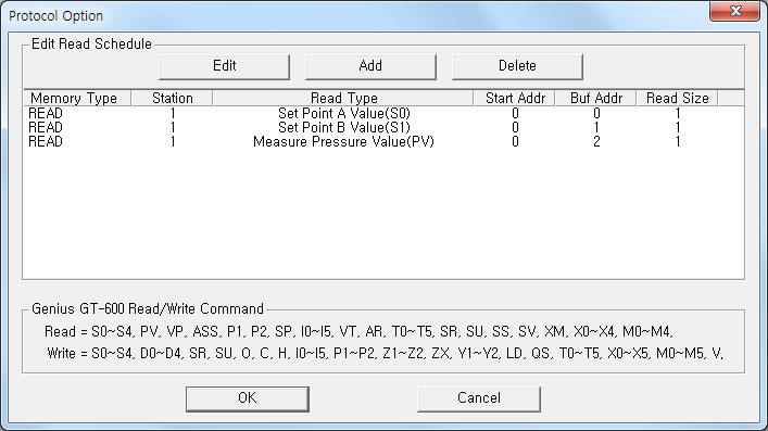 |
| <Figure 2> Example of Genius GT-600 communication driver’s Option dialogue box |
You can set read schedule by using ![]() ,
, ![]() ,
, ![]() button and listbox of <Figure
2>.
button and listbox of <Figure
2>.
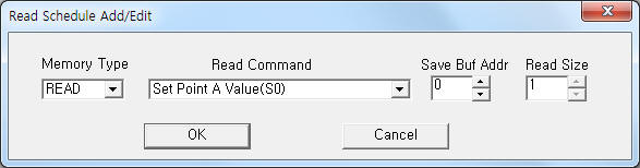 |
| <Figure 3> Example of Genius GT-600 communication driver’s read schedule Add/Edit dialogue box |
When you click Add button or Edit button in dialogue box of <Figure 2>, dialogue box of <Figure 3> is shown.
You can write setting value by using write settings.
Digital Write
Digital write and Analog write have the same setting parameters except output value(0 or 1).
Analog Write
Analog write setting parameters are as follows:
1) PORT Port no. (0 ~ 255)
2) STATION Don't care.
3) ADDRESS Don't care.
4) Extra1 Write command = S0~S4, D0~D4, SR, SU, O, C, H, I0~I5, P1~P2, Z1~Z2, ZX, Y1~Y2, LD, QS, T0~T5, X0~X5, M0~M5, V. ( Refer to <Table 2> )
5) Extra2 Number of decimal point(0 ~ 3) when R0 ~ R4, I0 ~ I5, P1 ~ P2, X0 ~ X5, M0 ~ M5 Write command.
<Table 2> is setting range and contents for each write command.
| Write Command(Extra1) | Contents | Extra2 | Range of output value |
| S0 ~ S4 | Write of Set Point A~E value | 0 ~ 3 : Number of decimal point | Float |
| D0 ~ D4 | Set Point A~E selection | Don't care | Don't care |
| SR | Write of Sensor Range | 0 = 0.1, 1 = 0.2,
2 = 0.5, 3 = 1, 4 = 2, 5 = 5, 6 = 10, 7 = 50, 8 = 100, 9 = 500, 10 = 1000, 11 = 5000, 12 = 10000, 13 = 1.33, 14 = 2.66, 15 = 13.33, 16 = 133.3, 17 = 1333, 18 = 6666, 19 = 13332 |
|
| SU | Write of Sensor Unit | 0 = Torr, 1 = mTorr, 2 = mBar, 3 = µµbar, 4 = kPa, 5 = Pa, 6 = cmH2O, 7 = inH2O |
|
| O | Open Valve command | Don't care | |
| C | Close Valve command | ||
| H | Stop ValVe command | ||
| I0 ~ I5 | Write of Softstart rate for Set Point A~E | 0 ~ 3 : Number of decimal point | Float |
| P1 ~ P2 | Write of Low/High threshold process limit | ||
| Z1 | Zero the Sensor command | Don't care | Don't care |
| Z2 | Zero the Analog Set Point Input command | ||
| ZX | Zero Cancellation command | ||
| Y1 | Sensor Span Calibration command | ||
| Y2 | Analog Set Point Span Calibration command | ||
| LD | Load Default setting command | ||
| QS | Calibration & Setup Data Save function command | ||
| T0~T4 | Write of Set Point A~E Type | 0 = position, 1 = pressure |
|
| T5 | Write of Set Point Analog Type | ||
| X0 ~ X4 | Write of Lead A~E value | 0 ~ 3 : Number of decimal point | Float |
| X5 | Write of Analog Point Lead value | ||
| M0 ~ M4 | Write of Gain A~E value | ||
| M5 | Write of Analog Point Gain value | ||
| V | Valve Calibration Execution command | Don't care | Don't care |
| <Table 2> Setting range and contents for each write command | |||
Write example 1)
PORT : 0 STATION : 0 ADDRESS : 0000 EXTRA1 : R1 EXTRA2 : 2
The setting parameter shown above is setting example for Set Point B value(output value's number of decimal point = 2).
Write example 2)
PORT : 0 STATION : 0 ADDRESS : 0000 EXTRA1 : C EXTRA2 : 0
The setting parameter shown above is control example of Close Valve.
Write example 3)
PORT : 0 STATION : 0 ADDRESS : 0000 EXTRA1 : X2 EXTRA2 : 2
The setting parameter shown above is setting example for Lead C value(output value's number of decimal point = 2).
Connection of communication cable and main power are as follows.
Connection of communication cable
Please connect RS-232C communication cable to 25 pin RS-232C socket of Genius GT-600 controller.
Connection of main power
Please connect 15 V DC main power to 25 pin RS-232C socket such as <Figure 4>.
<Figure 4> is appearence of Genius GT-600 controller.
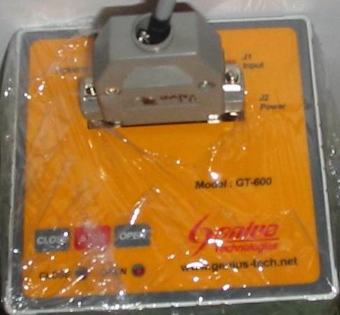 |
| <Figure 4> Appearence of Genius GT-600 controller |