G-IT Client communication driver is the driver to communicate with G-IT server of Hancess Co., Ltd. in Korea.
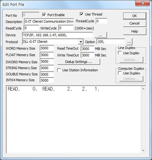
<Figure 1> is read setting example of G-IT Client communication driver.
 |
| <Figure 1> Read setting example of G-IT Client communication driver |
Device part of <Figure 1> input Device type(TCP/IP), IP address of PLC(192.168.1.47), service port of TCP/IP protocol (fixed to 6000),respectively, according to setting of Server.
Also you can set 'save start position of lighting lamp status' (0 ~ 9999, default = 100) by using option part.
Note) G-IT Client communication driver request lamp status data from server.
The sending lamp status data use WORD memory data.(saved data from 'SCADA Server program', etc)
Lamp status data save by bit, also one lamp ID data save at one word.
So you can save 256 word data or 256 lamp ID value.
Example) When 'save start position of lighting lamp status' address = 100,
100 word address = 0 lamp ID value,
101 word address = 1 lamp ID value,
¡¦.
355 word address = 255 lamp ID value.
G-IT Client communication driver read schedule
Read schedule setting parameters are as follows:
1) STATION – Don't care.
2) Read command – Fixed to 'READ'. ( Refer to <Table 1> )
3) Read lamp ID – Lamp ID = 0 ~ 255 .
4) Save Start Address for Communication Server – saveing start address of Communication Server.
5) Read Size – Fixed to 1.
Read schedule example)
READ, 0, READ, 2, 2, 1,
<Table 1> is data saving address and contents of G-IT Client communication driver.
| Read command | Contents | Data Saving Address | Remarks |
| READ | G-IT Lamp status request command | Start Add + 0 : G-IT lamp illuminance value | 1 ~ 10 : 10 ~ 100% illuminance , 0 : off |
| <Table 1> Data saving address and contents of G-IT Client communication driver | |||
G-IT Client communication driver store the same data in WORD, DWORD, FLOAT memory, but the data formats are different.
If you click the icon ![]() in protocol option part, you
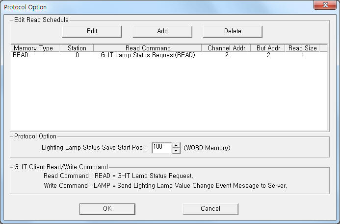
can see the dialogue box such as <Figure 2>. you can also set read schedule by
using this part.
in protocol option part, you
can see the dialogue box such as <Figure 2>. you can also set read schedule by
using this part.
 |
| <Figure 2> Example of G-IT Client communication driver¡¯s Option dialogue box |
You can set read schedule by using ![]() ,
, ![]() ,
, ![]() button and listbox of <Figure
2>.
button and listbox of <Figure
2>.
Also you can set save start position of lighting lamp status at the part of ¡®Lighting Lamp Status Save Start Pos¡¯ shown in <Figure 2>.
 |
| <Figure 3> Example of G-IT Client communication driver¡¯s read schedule Add/Edit dialogue box |
When you click Add button or Edit button in dialogue box of <Figure 2>, dialogue box of <Figure 3> is shown.
You can execute event command by using write settings.
Digital Write
Digital write and Analog write have the same setting parameters except output value(0 or 1).
Analog Write
Analog write setting parameters are as follows:
1) PORT Port no. (0 ~ 255)
2) STATION Don't care.
3) ADDRESS Lamp ID = 0 ~ 255 .
4) Extra1 Write command = LAMP. ( Refer to <Table 2> )
5) Extra2 Don't care.
<Table 2> is setting address and contents for write command.
| Write command | Contents | Address | Remarks |
| LAMP | Event send command | 0 ~ 255(decimal unit) Lamp ID |
When the lamp ID value has been changed, after changing the WORD memory(specified lamp ID address), send 'event command' after setting lamp ID value(Address). |
| <Table 2> Setting address and contents for write command | |||
Write example 1)
PORT:0, station:0, ADDRESS:0001, Extra1: LAMP, Extra2 : 0
The setting parameter shown above is event command seding example(to server) for 1 lamp ID.
The sending value for event command get WORD memory at specified lamp ID address.
So, you have to change the lamp ID status value before event command.