GMPC II communication driver is the driver to communicate with power meter GIMAC/GIMACII/GIMACIII/WDC-3000 model of LSIS Co., Ltd. in Korea.
WDC-3000 model communicate with GMPC controller( GMPC I, GMPC II, GMPC III, GMPC V, ... ) and computer read and write GMPC's data.
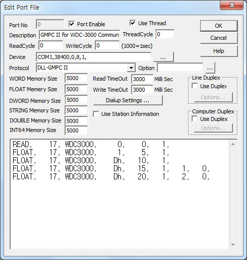
<Figure 1> is read setting example of GMPC II communication driver for WDC-3000 model.
|
|
| <Figure 1> Read setting example of GMPC II communication driver for WDC-3000 model |
Device part of <Figure 1> input Com Port(COM1 or TCP/IP, UDP/IP, etc), Baud Rate(38400), Parity Bit(0), Data Bit(8), Stop Bit(1) respectively according to setting of GMPC.
Baud rate, parity bit, data bit, stop bit can set by using switch of rear or front panel(GMPC controller).
GMPC II communication driver read schedule for uRTU or WDC-3000
Read schedule setting parameters are as follows:
1) STATION – WDC-3000 controller station number = 0 ~ 255.
2) Controller Model – Model = WDC3000 (when using WDC-3000 model).
3) Read data type – Data type = 0, 1, 2, 3.... ( Cmd - 10h, refer to reference manual of WDC-3000)
4) Save Start Address for Communication Server – saveing start address of Communication Server.
5) Read Size – Read size. Fixed according to read data type. ( Refer to <Table 1> )
6) Sub1 command - Input Sub1 command according to controller model.
7) Sub2 command - Input Sub 2 command according to controller model. ( 1 ~ 100, data type = 14, Sub1 = 1 )
Read schedule example)
READ, 17, WDC3000, 0, 0, 1,
FLOAT, 17, WDC3000, 1, 5, 1,
FLOAT, 17, WDC3000, Dh, 10, 1,
FLOAT, 17, WDC3000, Dh, 15, 1, 1, 0,
FLOAT, 17, WDC3000, Dh, 20, 1, 2, 0,
<Table 1> is data saving address and contents for each read type.
Note) Data type = Cmd number - 10h. Please refer to WDC-3000 reference manual for more information about Cmd, Sub1, Sub2, etc.
| Data type | Sub1 | Contents | Data size and unit | Data Saving Address |
| 0 | - | Device ID or DC status | 2 BYTE | Start Add + 0 = device ID, Start Add + 1 = DC status ( 0, 1 Bit = alarm status, 0 : normal, 1~3 :alarm, 2 Bit = control mode, 0 : manual, 1 : auto, 3 Bit = correction value status, 0 : normal, 1 : error, 4 Bit = system status, 0 : normal, 1 : error) |
| 1 | - | predictive power, reference power, current power | 3 Float data |
Start Add + 0 = predictive power, Start Add + 1 = reference power, Start Add + 2 = current power |
| 2 | - | Elapsed demand time and current time | 2 WORD + 4 BYTE |
Start Add + 0 = demand time (WORD unit), Start Add + 1 = DC time year(WORD unit), Start Add + 2 ~ 6 = DC time month,dat,hour,minute,second, Start Add + 7 = DC time data of the week(BYTE) |
| 3 | - | Load and communication status 1 ~ 6 load connection status(0 : don't connection,1 : connection) load status (0 : close,1 : input) |
12 BYTE | Start Add + 0 = 1 ~ 8 load connection status, Start Add + 1 = 1 ~ 8 load status, …, Start Add + 10 = 41 ~ 48 load connection status, Start Add + 11 = 41 ~ 48 load status |
| 4 | - | 12 BYTE | Start Add + 0 = 49 ~ 56 load connection status, Start Add + 1 = 49 ~ 56 load status, …, Start Add + 10 = 89 ~ 96 load connection status, Start Add + 11 = 89 ~ 96 load status |
|
| 5 | - | 12 BYTE | Start Add + 0 = 97 ~ 104 load connection status, Start Add + 1 = 97 ~ 104 load status, …, Start Add + 10 = 137 ~ 144 load connection status, Start Add + 11 = 137 ~ 144 load status |
|
| 6 | - | 12 BYTE | Start Add + 0 = 145 ~ 152 load connection status, Start Add + 1 = 145 ~ 152 load status, …, Start Add + 10 = 185 ~ 192 load connection status, Start Add + 11 = 185 ~ 192 load status |
|
| 7 | - | 12 BYTE | Start Add + 0 = 193 ~ 200 load connection status, Start Add + 1 = 193 ~ 200 load status, …, Start Add + 10 = 233 ~ 240 load connection status, Start Add + 11 = 233 ~ 240 load status |
|
| 8 | - | 4 BYTE | Start Add + 0 = 241 ~ 248 load connection status, Start Add + 1 = 241 ~ 248 load status, Start Add + 2 = 249 ~ 255 load connection status, Start Add + 3 = 249 ~ 255 load status |
|
| 13(Dh) | 0 ~ 3 | Read of weekdays target power of spring, summer, autumn, winter |
3 Float data | Start Add + 0 = light load, Start Add + 1 = middle load, Start Add + 2 = max load |
| 4 ~ 7 | Read of weekend(holiday) target power of spring, summer, autumn, winter |
3 Float data | Start Add + 0 = light load, Start Add + 1 = middle load, Start Add + 2 = max load |
|
| 8 | Read of DC setting | 1 DWORD + 1 WORD + 4 BYTE |
Start Add + 0 = PCT ratio(DWORD), Start Add + 1 = pulse constant(WORD), Start Add + 2 = load control mode(BYTE), Start Add + 3 = alarm output(BYTE), Start Add + 4 = demand time limit(BYTE), Start Add + 5 = amount of power pulse type(BYTE) |
|
| 9 | Read of Load setting | 2 BYTE + 3 WORD |
Start Add + 0 = number of load(BYTE), Start Add + 1 = control method(BYTE), Start Add + 2 = control start time(WORD), Start Add + 3 = input time(WORD), Start Add + 4 = close time(WORD) |
|
| 16 | Read of load Enable/Disable 1 ~ 30 : Disable, 1 : Enable |
12 BYTE | Start Add + 0 = 1 ~ 8 setting, …, Start Add + 11 = 89 ~ 96 setting |
|
| 17 | 12 BYTE | Start Add + 0 = 97 ~ 104 setting, …, Start Add + 11 = 185 ~ 192 setting |
||
| 18 | 8 BYTE | Start Add + 0 = 193 ~ 200 setting, …, Start Add + 6 = 241 ~ 248 setting, Start Add + 7 = 249 ~ 255 setting |
||
| 14(Eh) | 0 | Read of count of event data | 1 BYTE | Start Add + 0 = count of event (1 ~ 100) |
| 14(Eh) | 1 | Read of event data | 1 BYTE + 1 WORD + 9 BYTE |
Start Add + 0 = event number (1 ~ 100), Start Add + 1 = control time year(WORD), Start Add + 2 ~ 6 = control time month,day,hour,minute,second, Start Add + 7 = control ID, Start Add + 8 = control position, Start Add + 9 = control status, Start Add + 10 = control result |
| <Table 1> Data saving address and contents for each read type | ||||
GMPC II communication driver store the same data in WORD, DWORD, FLOAT memory, but the data format are different.
If you click the icon ![]() in protocol option part, you
can see the dialogue box such as <Figure 2>. you can also set read schedule by
using this part.
in protocol option part, you
can see the dialogue box such as <Figure 2>. you can also set read schedule by
using this part.
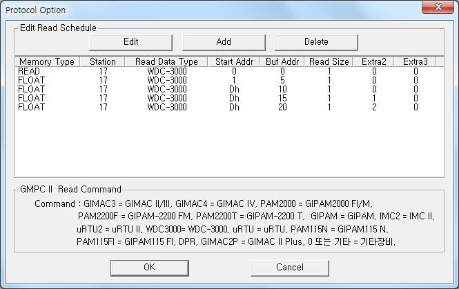 |
| <Figure 2> Example of GMPC II communication driver’s Option dialogue box |
You can set read schedule by using ![]() ,
, ![]() ,
, ![]() button and listbox of <Figure
2>.
button and listbox of <Figure
2>.
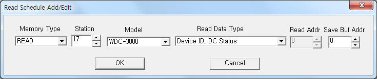 |
| <Figure 3> Example of GMPC II communication driver’s read schedule Add/Edit dialogue box |
When you click Add button or Edit button in dialogue box of <Figure 2>, dialogue box of <Figure 3> is shown.
You can write WDC-3000 equipment's setting value by using write settings.
Note) Write for WDC-3000 can control when the equipment's setting is 'remote'.
Digital Write
Digital write setting parameters are as follows:
1) PORT Port no. (0 ~ 255)
2) STATION WDC-3000 controller station number = 0 ~ 255.
3) ADDRESS Load control number(hex-decimal unit) when Extra2 = 0.
4) Extra1 Model name = WDC3000 . ( WDC-3000 model )
5) Extra2 Selection of Load control or Alarm reset.
0 – Load control command,
1 – Alarm reset command.
Write example 1)
PORT : 0 Station : 17, ADDRESS : 0001, EXTRA1 : WDC3000, EXTRA2 : 0
The setting parameter shown above is Load control example for 1 load. ( 17 controller station WDC-3000 )
Write example 2)
PORT : 0 Station : 17, ADDRESS : 0002, EXTRA1 : WDC3000, EXTRA2 : 0
The setting parameter shown above is Load control example for 2 load. ( 17 controller station WDC-3000 )
Write example 2)
PORT : 0 Station : 17, ADDRESS : 0000, EXTRA1 : WDC3000, EXTRA2 : 1
The setting parameter shown above is Alarm reset example of 17 controller station WDC-3000. ( only can set when Alarm output status = On )
Analog Write
Digital write setting parameters are as follows:
1) PORT Port no. (0 ~ 255)
2) STATION WDC-3000 controller station number = 0 ~ 255.
3) ADDRESS Output address according to Extra2.
4) Extra1 Model name = WDC3000 . ( WDC-3000 model )
5) Extra2 Setting type number = 0 ~ 9, 16, 17, 18, 255. ( refer to <Table 2> )
Note) Analog write for WDC-3000 controller made by writing after reading the setting value. ( except 255 setting type number )
Setting type number(Extra2) |
Contents |
Output format |
Address |
0 ~ 3 |
Write of weekdays target power of spring, summer, autumn, winter |
Float |
0 = light load, 1 = middle load, 2 = max load |
4 ~ 7 |
Write of weekend(holiday) target power of spring, summer, autumn, winter |
0 = light load, 1 = middle load, 2 = max load |
|
8 |
Write of DC setting |
According to Address |
0 = PCT ratio (DWORD), 1 = pulse constant(WORD), 2 = load control mode(BYTE), 3 = alarm output(BYTE), 4 = demand time limit(BYTE), 5 = amount of power pulse type(BYTE) |
9 |
Write of Load setting |
0 = number of load(BYTE), 1 = control method(BYTE), 2 = control start time(WORD), 3 = input time(WORD), 4 = close time(WORD)
|
|
16 |
Write of Load Enable/ Disable 1 ~ 3
0 : Disable, 1 : Enable |
BYTE
output value = 0 ~ 255 (8 (each bit) load status) |
0 = 1 ~ 8 setting, …, 11 = 89 ~ 96 setting |
17 |
0 = 97 ~ 104 setting, …, 11 = 185 ~ 192 setting |
||
18 |
0 = 193 ~ 200 setting, …, 6 = 241 ~ 248 setting, 7 = 249 ~ 255 setting |
||
255 |
Read of report data |
read |
save readed report data to memory(from Address) reading time for report data = 'work folder\SCAN\COMMxxx.ini' (xxx = port number, input method = refer to below ) |
| <Table 2> Setting element and command contents for Analog write | |||
Reading report time input method is as follows. ( Extra2 = 255, file name = ‘work folder\SCAN\COMMxxx.ini’ (xxx = port number)
(1) Input report time data to first line of file.
(2) Separate by using 'comma'( , ) each element.
(3) Input decimal unit every element.
(4) Input in year, month, day, hour, Seq order(5 element).
(5) Seq value : 0 = 5 minute, 10 minute, 1 = 15 minute, 20 minute, 2 = 25 minute, 30 minute, 3 = 35 minute, 40 minute, 4 = 45 minute, 50 minute, 5 = 55 minute, 0 minute.
Note) Readed data from Read of report data command( Extra2 = 255) save at 'Address + 0 ~ 1' WORD/FLOAT/DWORD memory. ( readed data = demand power, float unit )
Write example 1)
PORT : 0 Station : 17, ADDRESS : 0000, EXTRA1 : WDC3000, EXTRA2 : 0
The setting parameter shown above is 'low load weekday's target power of spring season' setting example for 17 controller station WDC-3000.
Write example 2)
PORT : 0 Station : 17, ADDRESS : 0001, EXTRA1 : WDC3000, EXTRA2 : 2
The setting parameter shown above is 'middle load weekday's target power of autumn season' setting example for 17 controller station WDC-3000.
Write example 3)
PORT : 0 Station : 17, ADDRESS : 0002, EXTRA1 : WDC3000, EXTRA2 : 7
The setting parameter shown above is 'max load weekend's target power of winter season' setting example for 17 controller station WDC-3000.
Write example 4)
PORT : 0 Station : 17, ADDRESS : 0000, EXTRA1 : WDC3000, EXTRA2 : 8
The setting parameter shown above is 'PCT ratio' setting example for 17 controller station WDC-3000.
Write example 5)
PORT : 0 Station : 17, ADDRESS : 0001, EXTRA1 : WDC3000, EXTRA2 : 8
The setting parameter shown above is 'pulse constant' setting example for 17 controller station WDC-3000.
Write example 6)
PORT : 0 Station : 17, ADDRESS : 0005, EXTRA1 : WDC3000, EXTRA2 : 8
The setting parameter shown above is 'amount of power pulse type' setting example for 17 controller station WDC-3000.
Write example 7)
PORT : 0 Station : 17, ADDRESS : 0004, EXTRA1 : WDC3000, EXTRA2 : 9
The setting parameter shown above is 'close time' setting example for 17 controller station WDC-3000.
Write example 8)
PORT : 0 Station : 17, ADDRESS : 0000, EXTRA1 : WDC3000, EXTRA2 : 16
The setting parameter shown above is '1 ~ 8 load's Enable/Disable status' setting example for 17 controller station WDC-3000. ( setting value = 0 ~ 255, 0 : Disable all load, 255 : Enable all load)
Write example 9)
PORT : 0 Station : 17, ADDRESS : 0001, EXTRA1 : WDC3000, EXTRA2 : 16
The setting parameter shown above is '9 ~ 15 load's Enable/Disable status' setting example for 17 controller station WDC-3000. ( setting value = 0 ~ 255, 0 : Disable all load, 255 : Enable all load)
Write example 10)
PORT : 0 Station : 17, ADDRESS : 0200, EXTRA1 : WDC3000, EXTRA2 : 255
The setting parameter shown above is 'Read of report data' example for 17 controller station WDC-3000. Reading time for report data = 'work folder\SCAN\COMM000.ini'.
After reading, the readed report data save 200 ~ 201 WORD, DWORD, FLOAT memory and delete the reading time file('work folder\SCAN\COMM000.ini').
Connection of main power and communication cable are as follows.
Connection of main power
Please connect 85 ~ 264V 50/60HZ AC power to main power socket at WDC-3000 controller's rear panel such as <Figure 4>.
<Figure 5> is appearance of WDC-3000 controller.
Note) WDC-3000 controller's Password input method : you can input 'password' by using 'UP' and 'Down' button of frong panel. ( Inital(default) Password : 0000 )
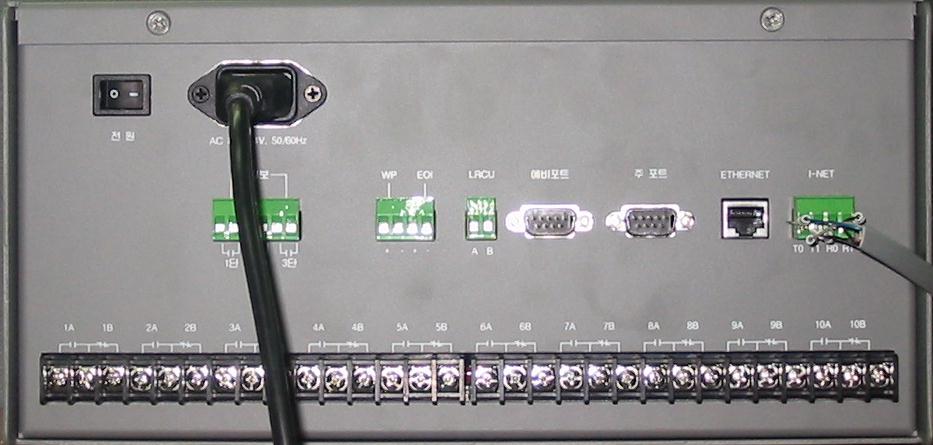 |
| <Figure 4> Connection example of main power and communication cable to WDC-3000 controller |
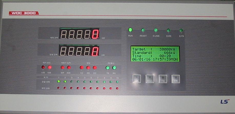 |
| <Figure 5> Appearance of WDC-3000 controller |
Connection of I-NET communication cable
Please connect I-NET RS-485 communication cable to 84 ( Rx0 ), 69 ( Rx1 ), 83 ( Tx0 ), 68 ( Tx1 ) connector such as <Figure 4>.
Note) When you connect WDC-3000 and GMPC, you have to connect Rx = Tx, Tx = Rx respectively. ( I-NET cable = offered by LSIS Co., Ltd. when you buying GMPC or WDC-3000)
<Figure 6> is apperance of GMPC V controller.
 |
| <Figure 6> Apperance of GMPCV controller |
Note) Password input method : you can input 'password' by using 4 button of frong panel. ( Inital(default) Password : press 'FUNCTION', 'SELECT', 'UP', 'ENTER' button 2 times by turns )
Setting of GMPC V)
1. Time & Date : Date and Time setting of GMPC V.
2. Model : Model, protocol and communication method of GMPC V.
Model | Protocol : select GMP(I-NET protocol of GMPC) or MODBUS protocol,
Model | Media : select communication media of GMPC V.
Model | Main Port : select Primary(P) or Secondary(S).
3. Serial : select Com1 or Com2 port of GMPC V.
4. Network(This) : select LAN1, LAN2 Ethernet port.
Network(This) | Ethernet Port : select primary ethernet port of GMPC V.
Network(This) | IP_0 : input IP Address of Primary Ethernet,
Network(This) | Port_0 No_0 : input Port number of Primary Ethernet,
Network(This) | Netmask_0 : input Subnet mask of Primary Ethernet,
Network(This) | Gateway_0 : input Gateway IP Address of Primary Ethernet,
Network(This) | Host_IP0 : input Host(PC, etc) IP Address of Primary Ethernet.
After setting GMPC V controller, save the setting by using 'ENTER' button.
Also, you have to reset(power off and power on) in order to apply the setting value. (don't reset, GMPC V use the old setting value)
Note) When you using the 'Ethernet' communication, you have to set Host(PC, etc) IP address at GMPC V controller.
Also if you don't use gateway at network, please set 'Gateway' IP address to '0.0.0.0'.
Note) You must input power for the first time of GIMAC-IV, etc, and input power GMPC V.
If you input power GMPC V the first and input GIMAC-IV, etc, GMPC V can't find connected equipment. So it may not be able to communicate with connected equipment.