GMPC II communication driver is the driver to communicate with power meter GIMAC/GIMACII/GIMACIII/GIPAM115 N model of LSIS Co., Ltd. in Korea.
GIPAM115 N model communicate with GMPC controller( GMPC I, GMPC II, GMPC III, GMPC V, ... ) and computer read and write GMPC's data.
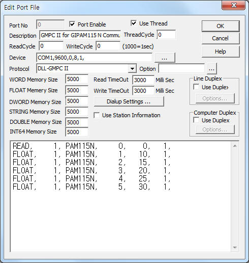
<Figure 1> is read setting example of GMPC II communication driver for GIPAM115 N model.
|
|
| <Figure 1> Read setting example of GMPC II communication driver for GIPAM115 N model |
Device part of <Figure 1> input Com Port(COM1 or TCP/IP, UDP/IP, etc), Baud Rate(9600), Parity Bit(0), Data Bit(8), Stop Bit(1) respectively according to setting of GMPC.
Baud rate, parity bit, data bit, stop bit can set by using switch of rear or front panel(GMPC controller).
GMPC II communication driver read schedule for GIPAM115 N
Read schedule setting parameters are as follows:
1) STATION – GIPAM115 N controller station number = 0 ~ 255.
2) Controller Model – Model = PAM115N (when using GIPAM115 N model).
3) Read data type – Data type = 0, 1, 2, 3.... ( Cmd - 10h, refer to reference manual of GIPAM115 FI )
4) Save Start Address for Communication Server – saveing start address of Communication Server.
5) Read Size – Read size. Fixed according to read data type. ( Refer to <Table 1> ~ <Table 2> )
6) Sub1 command - Input Sub1 command according to controller model.
7) Sub2 command - Input Sub 2 command according to controller model.
Read schedule example)
READ, 1, PAM115N, 0, 0, 1,
FLOAT, 1, PAM115N, 1, 10, 1,
FLOAT, 1, PAM115N, 2, 15, 1,
FLOAT, 1, PAM115N, 3, 20, 1,
FLOAT, 1, PAM115N, 4, 25, 1,
FLOAT, 1, PAM115N, 5, 30, 1,
<Table 1> is data saving address and contents for each read command.
<Table 2> is each bit value for I/O status read command.
Note) Data type = Cmd number - 10h. Please refer to GPAM115 N reference manual for more information about Cmd, Sub1, Sub2, etc.
GIPAM115 N model setting method : Select '4 COMM SETTING' by using SET or RUN button of GIPAM115N front panel.
Then select '6 I-NET TYPE' and set 'G115N' model.
| Data type | Sub1 | Sub2 | Contents | Data size and unit | Data Saving Address |
| 0 | - | Read of I/O status | 9 BYTE ( Bit data ) | Refer to <Table 2> |
|
| 1 | Read of R, S, T phase current | 3 Float data | Start Add + 0 ~ 2 : Ir, Is, It phase current |
||
| 2 | Read of Vab, Vbc, Vca voltage | Start Add + 0 ~ 2 : Vrs, Vst, Vtr voltage |
|||
| 3 | Power factor,active/reactive power | Start Add + 0 ~ 2 : power factor,total active/reactive power |
|||
| 4 | Frequency, amount of total active/reactive power | Start Add + 0 ~ 2 : frequency, amount of total active/reactive power |
|||
| 5 | Read of Va, Vb, Vc phase voltage | Start Add + 0 ~ 2 : Vr, Vs, Vt voltage |
|||
| 6 | zero-phase sequence voltage, max zero-phase sequence voltage |
2 Float data | Start Add + 0 : zero-phase sequence voltage Start Add + 1 : max zero-phase sequence voltage |
||
| 9 | 1 | 0 | Read of current SOE buffer | BYTE, WORD data | Start Add + 0 : occur hour Start Add + 1 : occur minute Start Add + 2 : occur second Start Add + 3 : occur milli second( 1/100 second ) Start Add + 4 ~ : status information 1 ~ 4( byte data ) (refer to reference manual for more information of status data) |
| <Table 1> Data saving address and contents for each read command | |||||
| Data Saving Address | Contents | Bit value for each bit |
Remarks |
| Start Add + 0 | Operation status of Relay | 7 Bit = Ir>, 6Bit = Is>, 5 Bit = It>, 6Bit = In>, 3 Bit = Ir>>, 2 Bit = Is>>, 1 Bit = It>>, 2 Bit = In>>, |
|
| Start Add + 1 | 7 Bit = OVR, 6 Bit = UVR, 5 Bit = VG>, 4 Bit = SGR, 3 Bit = VG>>, 2 Bit = POR, 1 Bit = 1, 0 Bit = Sys., |
|
|
| Start Add + 2 | CB status | 7 Bit = 1, 6 Bit = 1, 5 Bit = Aux_DI, 4 Bit = On out, 3 Bit = Off out, 2 Bit = Local, 1 Bit = On in, 0 Bit = Off in., |
Remote = 1, Local = 0 |
| Start Add + 3 | Reset/Clear status | 7 Bit = SOE, 6 Bit = R’y Set, 5 Bit = L-Rst, 4 Bit = R-Rst, 3 Bit = Local, 2 ~ 0 Bit = Clear Command Code, |
Local = valid only when 'Clear Command Code' Clear Command Code 0 = Wh Clear, 1 = Clear VARH, 2 = SOE Buffer Clear, 3 = CB On Counter Clear, 4 = CB On Time Clear, 5 = VO. Max Clear, 6 = All Clear, 7, other = Clear Nothing |
| Start Add + 4 | GIPAM internal Error Code | - |
|
| Start Add + 5 | |||
| <Table 2> Each bit value for I/O status read command | |||
GMPC II communication driver store the same data in WORD, DWORD, FLOAT memory, but the data format are different.
If you click the icon ![]() in protocol option part, you
can see the dialogue box such as <Figure 2>. you can also set read schedule by
using this part.
in protocol option part, you
can see the dialogue box such as <Figure 2>. you can also set read schedule by
using this part.
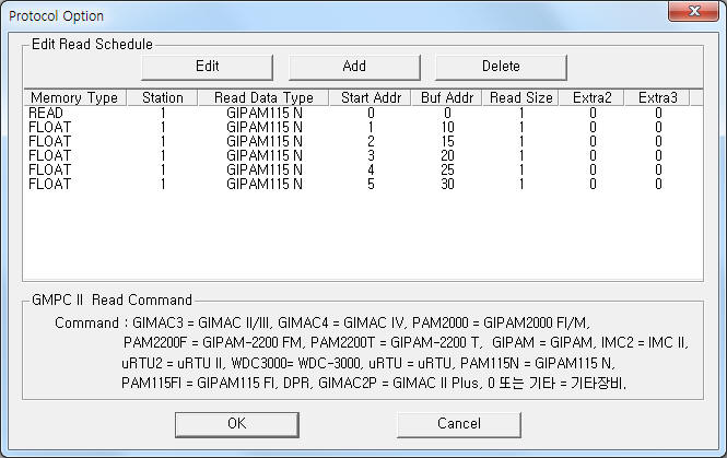 |
| <Figure 2> Example of GMPC II communication driver’s Option dialogue box |
You can set read schedule by using ![]() ,
, ![]() ,
, ![]() button and listbox of <Figure
2>.
button and listbox of <Figure
2>.
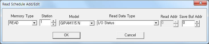 |
| <Figure 3> Example of GMPC II communication driver’s read schedule Add/Edit dialogue box |
When you click Add button or Edit button in dialogue box of <Figure 2>, dialogue box of <Figure 3> is shown.
You can write GIPAM115 N equipment's setting value by using write settings.
Note) Write for GIPAM115 N can control when the equipment's setting is 'remote'.
Digital Write
Digital write setting parameters are as follows:
1) PORT Port no. (0 ~ 255)
2) STATION GIPAM115 N controller station number = 0 ~ 255.
3) ADDRESS Reset type, refer to <Table 3>.
4) Extra1 Model name = PAM115N . ( GIPAM115 N model )
PAM115N – reset(or other ) command for GIPAM115 N,
CB – CB Close/Open control command,(output value : 1 = Close, 0 = Open)
CBON – CB Close control command,
CBOFF – CB Open control command.
5) Extra2 Don't care.
Address |
Command contents |
0002 |
Relay Fault Reset |
0003 |
Clear WH |
0004 |
Clear VARH |
0005 |
Clear All SOE Data |
0006 |
Clear CB On Counter |
0007 |
Clear CB On Time |
0008 |
Clear VO. Max |
0009 |
Clear Backup Data |
| <Table 3> Setting element and command contents for Digital write | |
Write example 1)
PORT : 0 Station : 1, ADDRESS : 0000, EXTRA1 : CBOFF, EXTRA2 : 0
The setting parameter shown above is CB open control example for 1 controller station GIPAM115 N.
CB open write command can control when the controller's setting is 'remote'
Write example 2)
PORT : 0 Station : 1, ADDRESS : 0001, EXTRA1 : CBON, EXTRA2 : 0
The setting parameter shown above is CB close control example for 1 controller station GIPAM115 N.
CB close write command can control when the controller's setting is 'remote'.
Write example 3)
PORT : 0 Station : 1, ADDRESS : 0002, EXTRA1 : PAM115N, EXTRA2 : 0
The setting parameter shown above is Relay Fault reset example for 1 controller station GIPAM115 N.
Write example 4)
PORT : 0 Station : 1, ADDRESS : 0003, EXTRA1 : PAM115N, EXTRA2 : 0
The setting parameter shown above is WH clear example for 1 controller station GIPAM115 N.
Analog Write
GMPC II communication driver for GIPAM115 N model don't support analog write.