GMPC II communication driver is the driver to communicate with power meter GIMAC/GIMACII/GIMACIII/IMC II ( Intelligent Motor Controller ) model of LSIS Co., Ltd. in Korea.
IMC II model communicate with GMPC controller( GMPC I, GMPC II, GMPC III, GMPC V, ... ) and computer read and write GMPC's data.
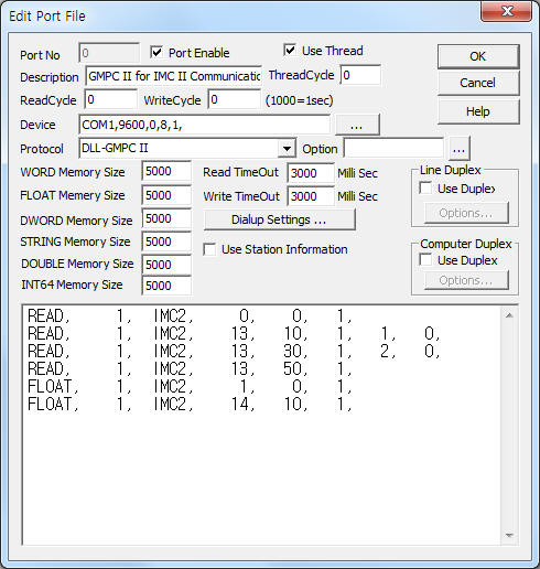
<Figure 1> is read setting example of GMPC II communication driver for IMC II model.
|
|
| <Figure 1> Read setting example of GMPC II communication driver for IMC II model |
Device part of <Figure 1> input Com Port(COM1 or TCP/IP, UDP/IP, etc), Baud Rate(9600), Parity Bit(0), Data Bit(8), Stop Bit(1) respectively according to setting of GMPC.
Baud rate, parity bit, data bit, stop bit can set by using switch of rear or front panel(GMPC controller).
GMPC II communication driver read schedule for IMC II
Read schedule setting parameters are as follows:
1) STATION – IMC II controller station number = 0 ~ 255.
2) Controller Model – Model = IMC2 (when using IMC II model).
3) Read data type – Data type = 0, 1, 13, 14.... ( Cmd - 10h, refer to reference manual of IMC II )
4) Save Start Address for Communication Server – saveing start address of Communication Server.
5) Read Size – Read size. Fixed according to read data type. ( Refer to <Table 1> ~ <Table 8> )
6) Sub1 command - Input 0 ~ 2 Sub1 command when 13 or 14 data type.
Read schedule example)
READ, 1, IMC2, 0, 0, 1,
READ, 1, IMC2, 13, 10, 1, 1, 0,
READ, 1, IMC2, 13, 30, 1, 2, 0,
READ, 1, IMC2, 13, 50, 1,
FLOAT, 1, IMC2, 1, 0, 1,
FLOAT, 1, IMC2, 14, 10, 1,
<Table 1> is read/write data element for IMC II controller.
<Table 2> ~ <Table 8> are data saving address and contents for 0, 1,13, 14 data type.
| Data type | Sub1 | Contents | Data unit | Data size | Remarks |
| 0 | Don't care | Read of I/O status | Bit | 6 Byte | Refer to <Table 2> |
| 1 | Read of current | Float | 3 Float | Refer to <Table 3> | |
| 13 | 0 | Read or write of setting value 1 | Byte/Bit,... | 10 Byte, 1 Bit, 1 Word | Refer to <Table 4> |
| 1 | Read or write of setting value 2 | Byte/Bit,... | 10 Byte, 1 Word | Refer to <Table 5> | |
| 2 | Read or write of setting value 3 | Word | 3 Word | Refer to <Table 6> | |
| 14 | 0 | Read of fault current | Float | 3 Float | Refer to <Table 7> |
| 1 | Read or write of setting value fault ground current current | Float/Word/Byte | 1 Float, 1 Word, 1Byte | Refer to <Table 8> | |
| <Table 1> Read/write data element for IMC II controller | |||||
Data Saving Address |
Contents |
Range |
Remarks |
Start Add + 0 |
Operating status |
1h, 2h, 4h, 8h |
0 Bit = On, 1 Bit = Rev, 2 Bit = Stop, 3 Bit = Reset |
Start Add + 1 |
Operating Mode |
1h, 2h, 4h, 8h |
0 Bit = Local, 1 Bit = MCC, 2 Bit = Remote, 3 Bit = Auto |
Start Add + 2 |
Trip phase display, pre-alarm |
1h, 10h, 20h, 30h |
0 Bit = over current, 4 ~ 5 Bit = R, S, T phase Trip |
Start Add + 3 |
Trip reason |
1h |
0 Bit = Timer2 Error(water purification plant mode ) |
Start Add + 4 |
1h, 2h, 4h, 8h, 10h, 20h, 40h, 80h |
0 Bit = over current, 1 Bit = open phase, 2 Bit = unblance, 3 Bit = low current, 4 Bit = Stall, 5 Bit = Lock, 6 Bit = ground, 7 Bit = negative phase, |
|
Start Add + 5 |
|
1h, 2h, 4h, 8h, 10h |
0 Bit = Input Fail, 1 Bit = Output Fail, 3 Bit = eeprom data init, 4 Bit = uncalibrated |
| <Table 2> Data saving address and contents for 0 data type | |||
Data Saving Address |
Contents |
Remarks |
Start Add + 0 ~ 2 |
R, S, T phase current |
Float value |
| <Table 3> Data saving address and contents for 1 data type | ||
Data Saving Address |
Contents |
Range |
Remarks |
Start Add + 0 |
Operating time |
1 ~ 60 |
|
Start Add + 1 |
CT Type |
0 or 1 |
CT Type 0 : 0.5 ~ 6 CT Type 1 : 5 ~ 60 real value = read value / 10 |
Start Add + 2 |
Rated current |
5 ~ 60 : CT = 0, 50 ~ 600 : CT = 1 |
|
Start Add + 3 |
Operation method |
1, 2, 4, 8 |
|
Start Add + 4 |
Operating time of reactor |
1 ~ 60 |
|
Start Add + 5 |
Operating time of Y |
|
|
Start Add + 6 |
Y-D switching time |
0, 1, 2 |
|
Start Add + 7 |
CT Ratio |
1 ~ 200 |
real value = read value / 5 |
Start Add + 8 |
Lock protection |
0 ~ 6 |
|
Start Add + 9 |
Lock delay time |
1 ~ 200 |
|
Start Add + 10 |
Stall protection |
0 ~ 3 |
|
Start Add + 11 |
Use of open phase protection function |
0, 1 |
|
| <Table 4> Data saving address and contents for 13 data type and 0 Sub1 | |||
Data Saving Address |
Contents |
Range |
Remarks |
Start Add + 0 |
Unblanced factor protection function |
0 ~ 3 |
|
Start Add + 1 |
Negative phase protection function |
0, 1 |
|
Start Add + 2 |
Ground protection function |
|
|
Start Add + 3 |
ZCT setting |
|
|
Start Add + 4 |
Setting of ground operation current |
0 ~ 6 |
|
Start Add + 5 |
Setting of ground operation time |
5, 10 ~ 100 |
real value = read value / 10 |
Start Add + 6 |
Ground Lock function when operating |
0, 1 |
|
Start Add + 7 |
Protection of low current |
0 ~ 9 |
|
Start Add + 8 |
voltage-dip compensation time |
0 ~ 10 |
|
Start Add + 9 |
Restart delay time |
0 ~ 300 |
Word data |
Start Add + 10 |
Over current Mode |
0, 1 |
|
| <Table 5> Data saving address and contents for 13 data type and 1 Sub1 | |||
Data Saving Address |
Contents |
Range |
Remarks |
Start Add + 0 ~ 2 |
Timer 1 ~ 3 Set |
0 ~ 300 |
Word |
| <Table 6> Data saving address and contents for 13 data type and 2 Sub1 | |||
Data Saving Address |
Contents |
Remarks |
Start Add + 0 ~ 2 |
R, S, T phase current |
Float data |
| <Table 7> Data saving address and contents for 14 data type and 0 Sub1 | ||
Data Saving Address |
Contents |
Remarks |
Start Add + 0 |
ground current |
Float value |
Start Add + 1 |
Trip cause ( refer to <Table 2> ) |
0 Bit = Timer2 Error( water purification plant mode ) |
Start Add + 2 |
0 Bit = over current, 1 Bit = open phase, 2 Bit = unblanced factor, 3 Bit = low current, 4 Bit = Stall, 5 Bit = Lock, 6 Bit = ground, 7 Bit = negative phase, |
|
Start Add + 3 |
Trip phase information |
0 Bit = over current, 4 ~ 5 Bit = R, S, T phase Trip |
| <Table 8> Data saving address and contents for 14 data type and 1 Sub1 | ||
You can write IMC II equipment's setting value by using write settings.
Note) Write for IMC II can control when the equipment's setting is 'remote'.
Digital Write
Digital write setting parameters are as follows:
1) PORT Port no. (0 ~ 255)
2) STATION IMC II controller station number = 0 ~ 255.
3) ADDRESS Setting data type.
0000 – Forward ON/Stop operation,
0001 – Reverse ON/Stop operation,
0002 – Reset.
4) Extra1 Model name = IMC2. ( IMC II model )
5) Extra2 Don't care.
Write example 1)
PORT : 0 Station : 1, ADDRESS : 0000, EXTRA1 : IMC2, EXTRA2 : 0
The setting parameter shown above is Forward ON/Stop operation control example for 1 controller station IMC II.
Forward ON/Stop operation write command can control when the controller's setting is 'remote'.
Write example 2)
PORT : 0 Station : 1, ADDRESS : 0001, EXTRA1 : IMC2, EXTRA2 : 0
The setting parameter shown above is Reverse ON/Stop operation control example for 1 controller station IMC II.
Reverse ON/Stop operation write command can control when the controller's setting is 'remote'.
Write example 3)
PORT : 0 Station : 1, ADDRESS : 0002, EXTRA1 : IMC2, EXTRA2 : 0
The setting parameter shown above is Reset control example for 1 controller station IMC II.
Reset write command can control when the controller's setting is 'remote'.
Digital Write
Digital write setting parameters are as follows:
1) PORT Port no. (0 ~ 255)
2) STATION IMC II controller station number = 0 ~ 255.
3) ADDRESS Setting data type.
0000 ~ 0010 – setting 1 ~ 2 (Extra2 = 0 ~ 1 ) writing address. refer to <Table 9> ~ <Table 10>,
0000 ~ 0002 – setting 3 writing address. refer to <Table 11>.
4) Extra1 Model name = IMC2. ( IMC II model )
5) Extra2 Selection of setting 1 ~ 3.
0 – setting value 1,
1 – setting value 2,
2 – setting value 3.
| Address | Contents | Output range | Remarks |
| 0000 | Operating time | 1 ~ 60 | |
| 0001 | Rated current | 5 ~ 60 : CT = 0,50 ~ 600 : CT = 1 | real value = output value / 10 |
| 0002 | Operation method | 1, 2, 4, 8 | |
| 0003 | Reactor operating time | 1 ~ 60 | |
| 0004 | Y operating time | ||
| 0005 | Y-D switching time | 0, 1, 2 | |
| 0006 | CT Ratio | 1 ~ 200 | real value = output value / 10 |
| 0007 | Lock protection | 0 ~ 6 | |
| 0008 | Lock delay time | 1 ~ 200 | |
| 0009 | Stall protection | 0 ~ 3 | |
| 0010 | Using of open phase protection function | 0, 1 | |
| <Table 9> Paramter range of setting value 1 for Analog write | |||
Address |
Contents |
Output range |
Remarks |
0000 |
Unblance protection function |
0 ~ 3 |
|
0001 |
Negative phase sequence protection function |
0, 1 |
|
0002 |
Ground protection function |
|
|
0003 |
Setting of ZCT |
|
|
0004 |
Setting of ground operation current |
0 ~ 6 |
|
0005 |
Setting of ground operating time |
5, 10 ~ 100 |
real value = output value / 10 |
0006 |
Gground Lock function when operation |
0, 1 |
|
0007 |
Protection of low current |
0 ~ 9 |
|
0008 |
Voltage-dip compensation time |
0 ~ 10 |
|
0009 |
Restart delay time |
0 ~ 300 |
|
0010 |
Over current mode |
0, 1 |
|
| <Table 10> Paramter range of setting value 2 for Analog write | |||
Address |
Contents |
Output range |
0000 ~ 0002 |
Timer 1 ~ 3 Set |
0 ~ 300 |
| <Table 11> Paramter range of setting value 3 for Analog write | ||
Write example 1)
PORT : 0 Station : 1, ADDRESS : 0000, EXTRA1 : IMC2, EXTRA2 : 0
The setting parameter shown above is Operating time setting( output range : 1 ~ 60 ) example for 1 controller station IMC II.
Write example 2)
PORT : 0 Station : 1, ADDRESS : 0006, EXTRA1 : IMC2, EXTRA2 : 0
The setting parameter shown above is CT Ratio setting( output range : 1 ~ 200 ) example for 1 controller station IMC II.
Write example 3)
PORT : 0 Station : 1, ADDRESS : 0009, EXTRA1 : IMC2, EXTRA2 : 1
The setting parameter shown above is Restart delay time setting( output range : 0 ~ 300 ) example for 1 controller station IMC II.
Write example 3)
PORT : 0 Station : 1, ADDRESS : 0000, EXTRA1 : IMC2, EXTRA2 : 2
The setting parameter shown above is Timer 1 setting( output range : 0 ~ 300 ) example for 1 controller station IMC II.
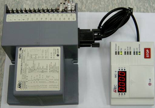
Connection of main power and communication cable are as follows.
Connection of main power
Please connect 110/220 V AC main power to 23, 24 connector at IMC II controller's rear panel such as <Figure 2>.
 |
| <Figure 4> Connection example of main power and communication cable to GIMAC-IV controller |
Connection of I-NET communication cable
Please connect I-NET RS-485 communication cable to 27(Rx0), 28(Rx1), 29(Tx0) , 30(Tx1) connector such as <Figure 2>.