GMPC II communication driver is the driver to communicate with power meter GIMAC/GIMACII/GIMACIII/GIMAC-IV model of LSIS Co., Ltd. in Korea.
GIMAC-IV model communicate with GMPC controller( GMPC I, GMPC II, GMPC III, GMPC V, ... ) and computer read and write GMPC's data.
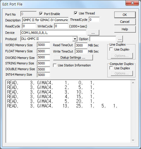
<Figure 1> is read setting example of GMPC II communication driver for GIMAC-IV model.
|
|
| <Figure 1> Read setting example of GMPC II communication driver for GIMAC-IV model |
Device part of <Figure 1> input Com Port(COM1 or TCP/IP, UDP/IP, etc), Baud Rate(9600), Parity Bit(0), Data Bit(8), Stop Bit(1) respectively according to setting of GMPC.
Baud rate, parity bit, data bit, stop bit can set by using switch of rear or front panel(GMPC controller).
GMPC II communication driver read schedule for GIMAC-IV
Read schedule setting parameters are as follows:
1) STATION – GIMAC-IV controller station number = 0 ~ 255.
2) Controller Model – Model = GIMAC4(when using GIMAC-IV model).
3) Read data type – Data type = 0, 1, 2, 3.... ( Cmd - 10h, refer to reference manual of GIMAC IV )
4) Save Start Address for Communication Server – saveing start address of Communication Server.
5) Read Size – Read size. Fixed according to read data type. ( Refer to <Table 1>, <Table 2> )
6) Sub1 command - Input Sub1 command according to controller model.
7) Sub2 command - Input Sub 2 command according to controller model.
Read schedule example)
READ, 3, GIMAC4, 1, 0, 1,
READ, 3, GIMAC4, 2, 5, 1,
READ, 3, GIMAC4, 3, 10, 1,
READ, 3, GIMAC4, 4, 15, 1,
READ, 3, GIMAC4, 5, 20, 1,
READ, 3, GIMAC4, 13, 25, 1, 5, 1,
<Table 1> is data saving address and contents for each read command.
<Table 2> is each bit value for I/O status read command.
Note) Data type = Cmd number - 10h. Please refer to GIMAC-IV reference manual for more information about Cmd, Sub1, Sub2, etc.
| Data type | Sub1 | Sub2 | Contents | Data Saving Address |
| 0 | 00 | 00 | Read of I/O status | Refer to <Table 2> |
| 1 | 00 | 00 | Read of R, S, T phase current | Start Add + 0 ~ 2 : R, S, T phase current |
| 2 | 00 | 00 | Read of Vab, Vbc, Vca voltage | Start Add + 0 ~ 2 : Vab, Vbc, Vca voltage |
| 3 | 00 | 00 | Power factor,active/reactive power | Start Add + 0 ~ 2 : power factor,total active/reactive power |
| 4 | 00 | 00 | Frequency, amount of total active/reactive power | Start Add + 0 ~ 2 : frequency, amount of total active/reactive power |
| 5 | 00 | 00 | Read of Va, Vb, Vc phase voltage | Start Add + 0 ~ 2 : Va, Vb, Vc voltage |
| 6 | 00 | 00 | Total apparent power, reverse active power quantity, zero-phase sequence voltage |
Start Add + 0 : total Total apparent power, Start Add + 1 : reverse active power quantity, Start Add + 2 : zero-phase sequence voltage |
| 01 | 00 | positive phase sequence voltage, negative phase sequence voltage, voltage unblanced factor |
Start Add + 0 : positive phase sequence voltage, Start Add + 1 : negative phase sequence voltage, Start Add + 2 : voltage unblanced factor |
|
| 02 | 00 | positive phase sequence current, negative phase sequence current, current unblanced factor |
Start Add + 0 : positive phase sequence current, Start Add + 1 : negative phase sequence current, Start Add + 2 : current unblanced factor |
|
| 03 | 00 | Vo max, Vo max time | Start Add + 0 ~ 8 : Vo max, Vo max time year, month, day, hour, minute, second, 0, 0, |
|
| 7 | 00 | 00 | A, B, C phase voltage | Start Add + 0 ~ 2 : A, B, C phase voltage |
| 01 | 00 | AB, BC, CA phase voltage | Start Add + 0 ~ 2 : AB, BC, CA phase voltage |
|
| 02 | 00 | A, B, C phase current | Start Add + 0 ~ 2 : A, B, C phase current |
|
| 8 | 00 | 00 | A, B, C phase active power | Start Add + 0 ~ 2 : A, B, C phase active power |
| 01 | 00 | A, B, C phase reactive power | Start Add + 0 ~ 2 : A, B, C phase reactive power |
|
| 02 | 00 | A, B, C phase apparent power | Start Add + 0 ~ 2 : A, B, C phase apparent power |
|
| 03 | 00 | A, B, C phase amount of active power | Start Add + 0 ~ 2 : A, B, C phase amount of active power |
|
| 04 | 00 | A, B, C phase amount of reactive power | Start Add + 0 ~ 2 : A, B, C phase amount of reactive power |
|
| 05 | 00 | A, B, C phase amount of reverse active power | Start Add + 0 ~ 2 : A, B, C phase amount of reverse active power |
|
| 06 | 00 | A, B, C phase current power factor | Start Add + 0 ~ 2 : A, B, C phase current power factor |
|
| 08 | 00 | GIMAC-IV operating time, CB ON time | Start Add + 0 ~ 1 : GIMAC-IV operating time, CB ON time |
|
| 09 | 00 | CB ON count, DO_0 ~ D0_1 count | Start Add + 0 ~ 5 : CB ON count, DO_0 ~ D0_1 ON count |
|
| 09 | 01 | DO_2 ~ D0_4 count | Start Add + 0 ~ 5 : DO_2 ~ D0_4 ON count |
|
| 09 | 02 | DO_5 ~ D0_7 count | Start Add + 0 ~ 1 : DO_2 ~ D0_7 ON count |
|
| 9 | 00 | 00 | A phase 1, 2, 3 voltage harmonic | Start Add + 0 ~ 2 : A phase 1, 2, 3 voltage harmonic |
| 00 | 01 | A phase 4, 5, 6 voltage harmonic | Start Add + 0 ~ 2 : A phase 4, 5, 6 voltage harmonic |
|
| 00 | 02 | A phase 7, 8, 9 voltage harmonic | Start Add + 0 ~ 2 : A phase 7, 8, 9 voltage harmonic |
|
| 00 | 03 | A phase 10, 11, 12 voltage harmonic | Start Add + 0 ~ 2 : A phase 10, 11, 12 voltage harmonic |
|
| 00 | 04 | A phase 13, 14, 15 voltage harmonic | Start Add + 0 ~ 2 : A phase 13, 14, 15 voltage harmonic |
|
| 01 | 00 | B phase 1, 2, 3 voltage harmonic | Start Add + 0 ~ 2 : B phase 1, 2, 3 voltage harmonic |
|
| 01 | 01 | B phase 4, 5, 6 voltage harmonic | Start Add + 0 ~ 2 : B phase 4, 5, 6 voltage harmonic |
|
| 01 | 02 | B phase 7, 8, 9 voltage harmonic | Start Add + 0 ~ 2 : B phase 7, 8, 9 voltage harmonic |
|
| 01 | 03 | B phase 10, 11, 12 voltage harmonic | Start Add + 0 ~ 2 : B phase 10, 11, 12 voltage harmonic |
|
| 01 | 04 | B phase 13, 14, 15 voltage harmonic | Start Add + 0 ~ 2 : B phase 13, 14, 15 voltage harmonic |
|
| 02 | 00 | C phase 1, 2, 3 voltage harmonic | Start Add + 0 ~ 2 : C phase 1, 2, 3 voltage harmonic |
|
| 02 | 01 | C phase 4, 5, 6 voltage harmonic | Start Add + 0 ~ 2 : C phase 4, 5, 6 voltage harmonic |
|
| 02 | 02 | C phase 7, 8, 9 voltage harmonic | Start Add + 0 ~ 2 : C phase 7, 8, 9 voltage harmonic |
|
| 02 | 03 | C phase 10, 11, 12 voltage harmonic | Start Add + 0 ~ 2 : C phase 10, 11, 12 voltage harmonic |
|
| 02 | 04 | C phase 13, 14, 15 voltage harmonic | Start Add + 0 ~ 2 : C phase 13, 14, 15 voltage harmonic |
|
| 03 | 00 | A phase 1, 2, 3 current harmonic | Start Add + 0 ~ 2 : A phase 1, 2, 3 current harmonic |
|
| 03 | 01 | A phase 4, 5, 6 current harmonic | Start Add + 0 ~ 2 : A phase 4, 5, 6 current harmonic |
|
| 03 | 02 | A phase 7, 8, 9 current harmonic | Start Add + 0 ~ 2 : A phase 7, 8, 9 current harmonic |
|
| 03 | 03 | A phase 10, 11, 12 current harmonic | Start Add + 0 ~ 2 : A phase 10, 11, 12 current harmonic |
|
| 03 | 04 | A phase 13, 14, 15 current harmonic | Start Add + 0 ~ 2 : A phase 13, 14, 15 current harmonic |
|
| 04 | 00 | B phase 1, 2, 3 current harmonic | Start Add + 0 ~ 2 : B phase 1, 2, 3 current harmonic |
|
| 04 | 01 | B phase 4, 5, 6 current harmonic | Start Add + 0 ~ 2 : B phase 4, 5, 6 current harmonic |
|
| 04 | 02 | B phase 7, 8, 9 current harmonic | Start Add + 0 ~ 2 : B phase 7, 8, 9 current harmonic |
|
| 04 | 03 | B phase 10, 11, 12 current harmonic | Start Add + 0 ~ 2 : B phase 10, 11, 12 current harmonic |
|
| 04 | 04 | B phase 13, 14, 15 current harmonic | Start Add + 0 ~ 2 : B phase 13, 14, 15 current harmonic |
|
| 05 | 00 | C phase 1, 2, 3 current harmonic | Start Add + 0 ~ 2 : C phase 1, 2, 3 current harmonic |
|
| 05 | 01 | C phase 4, 5, 6 current harmonic | Start Add + 0 ~ 2 : C phase 4, 5, 6 current harmonic |
|
| 05 | 02 | C phase 7, 8, 9 current harmonic | Start Add + 0 ~ 2 : C phase 7, 8, 9 current harmonic |
|
| 05 | 03 | C phase 10, 11, 12 current harmonic | Start Add + 0 ~ 2 : C phase 10, 11, 12 current harmonic |
|
| 05 | 04 | C phase 13, 14, 15 current harmonic | Start Add + 0 ~ 2 : C phase 13, 14, 15 current harmonic |
|
| 06 | 00 | A, B, C phase voltage THD | Start Add + 0 ~ 2 : A, B, C phase voltage THD |
|
| 07 | 00 | A, B, C phase current THD | Start Add + 0 ~ 2 : A, B, C phase current THD |
|
| 08 | 00 | AB, BC, CA phase voltage THD | Start Add + 0 ~ 2 : AB, BC, CA phase voltage THD |
|
| 10(0Ah) | 00 | 00 | reference power, current power, predictive power | Start Add + 0 ~ 2 : reference power, current power, predictive power |
| 01 | 00 | Remain Demand time, A[0], A[1] current | Start Add + 0 ~ 3 : remain Demand time minute, second, A[0], A[1] current |
|
| 02 | 00 | Demand Ia, Demand Ia time | Start Add + 0 ~ 8 : Demand Ia, Demand Ia time year, month, day, hour, minute, second, 0, 0, |
|
| 02 | 01 | Demand Ib, Demand Ib time | Start Add + 0 ~ 8 : Demand Ib, Demand Ib time year, month, day, hour, minute, second, 0, 0, |
|
| 02 | 02 | Demand Ic, Demand Ic time | Start Add + 0 ~ 8 : Demand Ic, Demand Ic time year, month, day, hour, minute, second, 0, 0, |
|
| 03 | 00 | MAX Demand W, MAX Demand W time | Start Add + 0 ~ 8 : MAX Demand W, MAX Demand W time year, month, day, hour, minute, second, 0, 0, |
|
| 03 | 01 | MAX W, MAX W time | Start Add + 0 ~ 8 : MAX W, MAX W time year, month, day, hour, minute, second, 0, 0, |
|
| 13(0Dh) | 00 | 00 | Wiring type, frequency setting value | Start Add + 0 : Wiring type ( 1 = 3 phase 4 line, 2 = 3 phase 4 line Y, 3 = 3 phase 3 line delta, 4 = 1 phase 3 line, 5 = 1 phase 2 line ) Start Add + 1 : requency setting (50 or 60Hz) |
| 01 | 00 | PT, GPT, CT setting value | Start Add + 0 ~ 2 : PT, GPT, CT setting value |
|
| 02 | 00 | Bank count, Delay, setting value of bank 1 | Start Add + 0 : bank count Start Add + 1 : APFC ALARM RELAY(DO1~8) Start Add + 2 ~ 3 : bank 1 ON/OFF RELAY Setting Start Add + 4 : bank 1 volume |
|
| 02 | 01 | setting value of bank 2 ~ 3 | Start Add + 0 ~ 1 : bank 2 ON/OFF RELAY Setting Start Add + 2 : bank 2 volume Start Add + 3 ~ 4 : bank 3 ON/OFF RELAY Setting Start Add + 5 : bank 3 volume |
|
| 02 | 02 | setting value of bank 4 ~ 5 | Start Add + 0 ~ 1 : bank 4 ON/OFF RELAY Setting Start Add + 2 : bank 4 volume Start Add + 3 ~ 4 : bank 5 ON/OFF RELAY Setting Start Add + 5 : bank 5 volume |
|
| 02 | 03 | setting value of bank 6 ~ 7 | Start Add + 0 ~ 1 : bank 6 ON/OFF RELAY Setting Start Add + 2 : bank 6 volume Start Add + 3 ~ 4 : bank 7 ON/OFF RELAY Setting Start Add + 5 : bank 7 volume |
|
| 02 | 04 | setting value of bank 8 | Start Add + 0 ~ 1 : bank 8 ON/OFF RELAY Setting Start Add + 2 : bank 8 volume |
|
| 03 | 00 | setting value of APFC Time | Start Add + 0 ~ 1 : APFC DELAY TIME, APFC DEAD TIME |
|
| 03 | 01 | setting value of APFC PF | Start Add + 0 ~ 2 : APFC MAX/MIN/ALARM PF value |
|
| 03 | 02 | setting value of APFC | Start Add + 0 ~ 2 : APFC Reverse/Low/R-Voltage Current Event (11h or 01h) Start Add + 3 ~ 5 : APFC Over Switch/Over PF/Low PF Current Event ( 01h) |
|
| 04 | 00 | Demand setting #1 | Start Add + 0 : Number of load for demand controller Start Add + 1 : Alarm number of demand controller Start Add + 2 ~ 3 : Load 1 On/Off Relay for demand controller Start Add + 4 ~ 5 : Load 2 On/Off Relay for demand controller Start Add + 6 ~ 7 : Load 3 On/Off Relay for demand controller Start Add + 8 ~ 9 : Load 4 On/Off Relay for demand controller Start Add + 10 ~ 11 : Load 5 On/Off Relay for demand controller |
|
| 04 | 01 | Demand setting #2 | Start Add + 0 ~ 1 : Load 6 On/Off Relay for demand controller Start Add + 2 ~ 3 : Load 7 On/Off Relay for demand controller Start Add + 4 ~ 5 : Load 8 On/Off Relay for demand controller Start Add + 6 ~ 7 : Demand Controller Alarm 1 ~ 2 Relay Start Add + 8 ~ 9 : Demand Controller Demand/Start time Start Add + 10 ~ 11 : Demand Controller Period/Delay time |
|
| 04 | 02 | Demand setting #3 | Start Add + 0 : Demand Controller target power |
|
| 05 | 00 | DI Set Status #1 | Start Add + 0 ~ 5 : DI 1 ~ 6 Set Status |
|
| 05 | 01 | DI Set Status #2 | Start Add + 0 ~ 1 : DI 7 ~ 8 Set Status |
|
| 06 | 00 | DO Set Status #1 | Start Add + 0 ~ 5 : DO 1 ~ 6 Set Status |
|
| 06 | 01 | DO Set Status #2 | Start Add + 0 ~ 1 : DO 7 ~ 8 Set Status |
|
| <Table 1> Data saving address and contents for each read command | ||||
Data Saving Address |
Bit position |
|||||||
7 |
6 |
5 |
4 |
3 |
2 |
1 |
0 |
|
Start Add + 0 |
DI_8 |
DI_7 |
DI_6 |
DI_5 |
DI_4 |
DI_3 |
DI_2 |
DI_1 |
Start Add + 1 |
Latch DI_8 |
Latch DI_7 |
Latch DI_6 |
Latch DI_5 |
Latch DI_4 |
Latch DI_3 |
Latch DI_2 |
Latch DI_1 |
Start Add + 2 |
DO_8 |
DO_7 |
DO_6 |
DO_5 |
DO_4 |
DO_3 |
DO_2 |
DO_1 |
Start Add + 3 |
CB On DI |
CB Off DI |
CB On DO |
CB Off DO |
- |
|||
Start Add + 4 |
Event |
- |
- |
R/L |
A/M |
- |
ALARM |
Sys Error |
Start Add + 5 |
Device ID ( 98h ) |
|||||||
| <Table 2> Each bit value for I/O status read command | ||||||||
GMPC II communication driver store the same data in WORD, DWORD, FLOAT memory, but the data format are different.
If you click the icon ![]() in protocol option part, you
can see the dialogue box such as <Figure 2>. you can also set read schedule by
using this part.
in protocol option part, you
can see the dialogue box such as <Figure 2>. you can also set read schedule by
using this part.
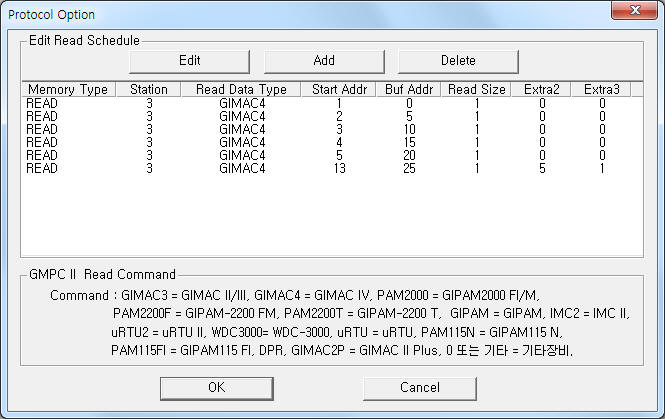 |
| <Figure 2> Example of GMPC II communication driver’s Option dialogue box |
You can set read schedule by using ![]() ,
, ![]() ,
, ![]() button and listbox of <Figure
2>.
button and listbox of <Figure
2>.
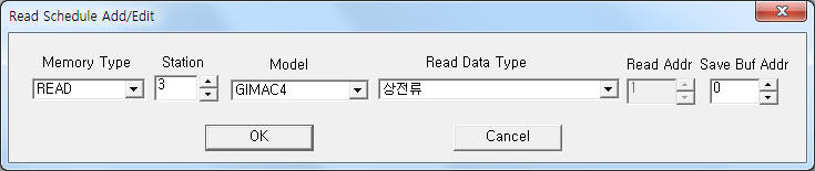 |
| <Figure 3> Example of GMPC II communication driver’s read schedule Add/Edit dialogue box |
When you click Add button or Edit button in dialogue box of <Figure 2>, dialogue box of <Figure 3> is shown.
You can write GIMAC-IV equipment's setting value by using write settings.
Digital Write
Digital write setting parameters are as follows:
1) PORT Port no. (0 ~ 255)
2) STATION GIMAC-IV controller station number = 0 ~ 255.
3) ADDRESS Setting data type(hex-decimal unit) number of Sub2, refer to <Table 3>.
4) Extra1 Model name = GIMAC4. ( GIMAC-IV model )
5) Extra2 Load control, Reset or Clear setting.
0 – Load control,
1 – Reset or Clear command.
Command |
Address(Sub2) number |
Contents |
Load control |
01h |
CB ON control |
02h |
CB OFF control |
|
10h |
DO 1 ON control |
|
11h |
DO 2 ON control |
|
12h |
DO 3 ON control |
|
13h |
DO 4 ON control |
|
14h |
DO 5 ON control |
|
15h |
DO 6 ON control |
|
16h |
DO 7 ON control |
|
17h |
DO 8 ON control |
|
18h |
DO 1 OFF control |
|
19h |
DO 2 OFF control |
|
1Ah |
DO 3 OFF control |
|
1Bh |
DO 4 OFF control |
|
1Ch |
DO 5 OFF control |
|
1Dh |
DO 6 OFF control |
|
1E6h |
DO 7 OFF control |
|
1Fh |
DO 8 OFF control |
|
Reset or Clear command |
00h |
Vo MAX reset |
01h |
DEMAND CURRENT reset |
|
02h |
MAX DEMAND W reset |
|
03h |
MAX W reset |
|
04h |
WH reset |
|
05h |
VARH reset |
|
06h |
rWH reset |
|
07h |
EVENT clear |
|
08h |
GiMAC-IV RUN TIME clear |
|
09h |
|
|
0Ah |
CB ON COUNT clear |
|
0Bh |
DO 1 ON COUNT clear |
|
0Ch |
DO 2 ON COUNT clear |
|
0Dh |
DO 3 ON COUNT clear |
|
0Eh |
DO 4 ON COUNT clear |
|
0Fh |
DO 5 ON COUNT clear |
|
10h |
DO 6 ON COUNT clear |
|
11h |
DO 7 ON COUNT clear |
|
12h |
DO 8 ON COUNT clear |
|
13h |
Change to Auto status |
|
14h |
Change to Manual status |
|
15h |
FAULT RESET |
|
| <Table 3> Setting element and data range for Digital write | ||
Note) Digital write for GIMAC-IV can control when the equipment's setting is 'remote'.
Write example 1)
PORT : 0 Station : 1, ADDRESS : 0001, EXTRA1 : GIMAC4, EXTRA2 : 0
The setting parameter shown above is CB ON control example for 1 controller station GIMAC IV.
CB ON write command can control when the controller's setting is 'remote'.
Write example 2)
PORT : 0 Station : 1, ADDRESS : 0002, EXTRA1 : GIMAC4, EXTRA2 : 0
The setting parameter shown above is CB OFF control example for 1 controller station GIMAC IV.
CB OFF write command can control when the controller's setting is 'remote'.
Write example 3)
PORT : 0 Station : 1, ADDRESS : 0010, EXTRA1 : GIMAC4, EXTRA2 : 0
The setting parameter shown above is DO 1 On control example for 1 controller station GIMAC IV.
DO 1 On write command can control when the controller's setting is 'remote' and current status is 'Off'.
Write example 4)
PORT : 0 Station : 1, ADDRESS : 0018, EXTRA1 : GIMAC4, EXTRA2 : 0
The setting parameter shown above is DO 1 Off control example for 1 controller station GIMAC IV.
DO 1 Off write command can control when the controller's setting is 'remote' and current status is 'On'.
Write example 5)
PORT : 0 Station : 1, ADDRESS : 0000, EXTRA1 : GIMAC4, EXTRA2 : 1
The setting parameter shown above is reset of Vo MAX value example for 1 controller station GIMAC IV.
Vo MAX value reset command can control when the controller's setting is 'remote'.
Write example 6)
PORT : 0 Station : 1, ADDRESS : 0010, EXTRA1 : GIMAC4, EXTRA2 : 1
The setting parameter shown above is a example of clear DO 6 On count.
Clear DO 6 On count command can control when the controller's setting is 'remote'.
Analog Write
GMPC II communication driver for GIMAC-IV model don't support analog write.
Connection of main power and communication cable are as follows.
Connection of main power
Please connect main power( 110 AC, etc ) to N, P connector at GIMAC-IV controller's rear panel such as <Figure 4>.
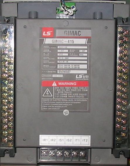
<Figure 5> is appearance of GIMAC-IV controller.
 |
| <Figure 4> Connection example of main power and communication cable to GIMAC-IV controller |
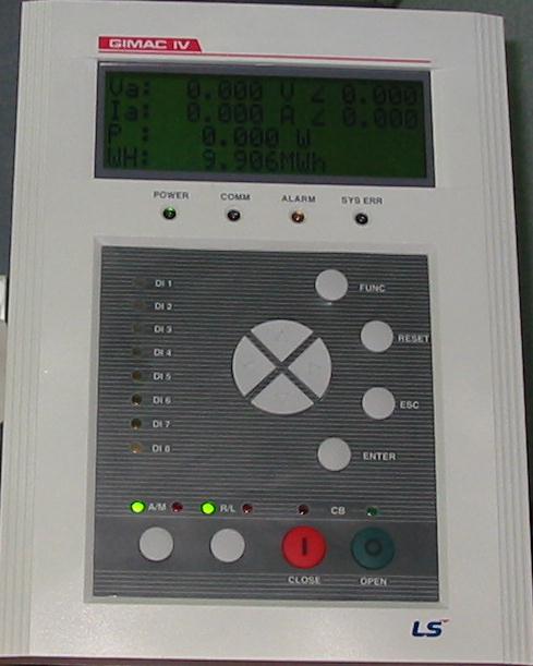 |
| <Figure 5> Appearance of GIMAC-IV controller |
Note) GIMAC-IV Password input method : you can input 'password' by using 'UP' and 'Down' button of frong panel. ( Inital(default) Password : 0000 )
Connection of I-NET communication cable
Please connect I-NET RS-485 communication cable to Rx0, Rx1, Tx0 , Tx1 connector such as <Figure 4>.
Note) When you connect GIMAC-IV and GMPC, you have to connect Rx = Tx, Tx = Rx respectively. ( I-NET cable = offered by LSIS Co., Ltd. when you buying GMPC or GIMAC-IV)
Connection of GMPC V almost equal with GMPC III. So you can refer to connection of GMPC III part.
<Figure 6> is apperance of GMPC V controller.
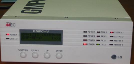 |
| <Figure 6> Apperance of GMPCV controller |
Note) Password input method : you can input 'password' by using 4 button of frong panel. ( Inital(default) Password : press 'FUNCTION', 'SELECT', 'UP', 'ENTER' button 2 times by turns )
Setting of GMPC V)
1. Time & Date : Date and Time setting of GMPC V.
2. Model : Model, protocol and communication method of GMPC V.
Model | Protocol : select GMP(I-NET protocol of GMPC) or MODBUS protocol,
Model | Media : select communication media of GMPC V.
Model | Main Port : select Primary(P) or Secondary(S).
3. Serial : select Com1 or Com2 port of GMPC V.
4. Network(This) : select LAN1, LAN2 Ethernet port.
Network(This) | Ethernet Port : select primary ethernet port of GMPC V.
Network(This) | IP_0 : input IP Address of Primary Ethernet,
Network(This) | Port_0 No_0 : input Port number of Primary Ethernet,
Network(This) | Netmask_0 : input Subnet mask of Primary Ethernet,
Network(This) | Gateway_0 : input Gateway IP Address of Primary Ethernet,
Network(This) | Host_IP0 : input Host(PC, etc) IP Address of Primary Ethernet.
After setting GMPC V controller, save the setting by using 'ENTER' button.
Also, you have to reset(power off and power on) in order to apply the setting value. (don't reset, GMPC V use the old setting value)
Note) When you using the 'Ethernet' communication, you have to set Host(PC, etc) IP address at GMPC V controller.
Also if you don't use gateway at network, please set 'Gateway' IP address to '0.0.0.0'.
Note) You must input power for the first time of GIMAC-IV, etc, and input power GMPC V.
If you input power GMPC V the first and input GIMAC-IV, etc, GMPC V can't find connected equipment. So it may not be able to communicate with connected equipment.