GMPC II communication driver is the driver to communicate with power meter GIMAC/GIMACII/GIMACIII/DPR model of LSIS Co., Ltd. in Korea.
DPR model communicate with GMPC controller( GMPC I, GMPC II, GMPC III, GMPC V, ... ) and computer read and write GMPC's data.
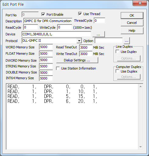
<Figure 1> is read setting example of GMPC II communication driver for DPR model.
|
|
| <Figure 1> Read setting example of GMPC II communication driver for DPR model |
Device part of <Figure 1> input Com Port(COM1 or TCP/IP, UDP/IP, etc), Baud Rate(9600), Parity Bit(0), Data Bit(8), Stop Bit(1) respectively according to setting of GMPC.
Baud rate, parity bit, data bit, stop bit can set by using switch of rear or front panel(GMPC controller).
GMPC II communication driver read schedule for DPR
Read schedule setting parameters are as follows:
1) STATION – DPR controller station number = 0 ~ 255.
2) Controller Model – Model = DPR(when using DPR model).
3) Read data type – Data type = 0, 1, 5, 6.... ( Cmd - 10h )
4) Save Start Address for Communication Server – saveing start address of Communication Server.
5) Read Size – Read size. Fixed according to read data type. ( Refer to <Table 1>, <Table 2> )
6) Sub1 command - Input Sub1 command according to controller model.
7) Sub2 command - Input Sub 2 command according to controller model.
Read schedule example)
READ, 1, DPR, 0, 0, 1,
READ, 1, DPR, 1, 10, 1,
READ, 1, DPR, 5, 15, 1,
READ, 1, DPR, 6, 20, 1,
<Table 1> is data saving address and contents for each read data type.
<Table 2> is data saving address and contents for status information.
Note) Data type = Cmd number - 10h. Please refer to DPR reference manual for more information about Cmd, Sub1, Sub2, etc.
| Data type | Extra2 | Extra3 | Contents |
Data size or unit | Data Saving Address |
| 0 | - | Status information( I/O,...) |
3 BYTE ( Bit data ) | refet to <Table 2> |
|
| 1 | Phase current |
3 Float data | Start Add + 0 ~ 2 : Ir, Is, It |
||
| 5 | Phase voltage |
Start Add + 0 ~ 2 : Vr, Vs, Vt |
|||
| 6 | Zero Sequence voltage, Zero Sequence current |
2 Float data | Start Add + 0 ~ 1 : Zero Sequence voltage and current |
||
| 9 | 1 | 0 | Read of SOE data |
Occur time(hour, minute, second, milli-second), 2 Byte(Bit data) status |
Start Add + 0 : hour Start Add + 1 : minute Start Add + 2 : second Start Add + 3 : milli-second(1/1000 second) Start Add + 4 : 7 ~ 4 Bit = In>>, It>>, Is>>, Ir>>, 3 ~ 0 Bit = In>, It>, Is>, Ir> Start Add + 5 : 7 ~ 5 Bit = 0, 4 Bit = Fault, 3 Bit = Local Fault Reset, 2 Bit = Remote, 1 Bit = Local, 0 Bit = Sys Fail |
| 3 | 0 | Delete current SOE data and read next data |
|||
| 2 | 0 | Delete current SOE data |
Don't exist |
|
|
| 10(0Ah) | 0 ~ 7 | 0 ~ 13(0Dh) | Read of Fault Record Data |
12 Byte fault record data (last data = 4Byte) |
Start Add + 0 : Sub Command 1 Start Add + 1 : Sub Command 2 Start Add + 2 : Device ID(refet to <Table 2>) Start Add + 3 ~ 14 : Fault record data |
| 13(0Dh) | 0 | 0 | Read of OCR Setting |
BYTE, WORD | Start Add + 0 : Ground fault function on/off (Byte data) Start Add + 1 : OCR Instantaneous element Lock(Byte, Low Nibble) Start Add + 2 : Time delay current(x 10) Start Add + 3 : Instantaneous current(x 10) Start Add + 4 : Inverse Time operation hour(x 100) Start Add + 5 : Definite Time operation hour(x 10) Start Add + 6 : Characteristic curve |
| 1 | 0 | Read of OCGR Setting |
BYTE, WORD | Start Add + 0 : Ground fault function on/off (Byte data) Start Add + 1 : OCGR Instantaneous Lock(Byte, High Nibble) Start Add + 2 : Time delay current(x 10) Start Add + 3 : Instantaneous current(x 10) Start Add + 4 : Inverse Time operation hour(x 100) Start Add + 5 : Definite Time operation hour(x 10) Start Add + 6 : Characteristic curve |
|
| 2 | 0 | Read of SGR Setting |
BYTE, WORD | Start Add + 0 : Operating voltage Start Add + 1 : Operatin current(x 10) Start Add + 2 : Operating time(x 10) Start Add + 3 : Relay characteristic angle |
|
| 3 | 0 | Read of OVR(UVR) Setting |
BYTE, WORD | Start Add + 0 : OVR/UVR function selection Start Add + 1 : OVR operating voltage Start Add + 2 : UVR operating voltage Start Add + 3 : OVR operating time(x 100) Start Add + 4 : UVR operating time(x 100) Start Add + 5 : Zero voltage LOCK |
|
| 4 | 0 | Read of OVR/UVR Setting |
BYTE, WORD | Start Add + 0 : - Start Add + 1 : OVR operating voltage Start Add + 2 : UVR operating voltage Start Add + 3 : OVR operating time(x 100) Start Add + 4 : UVR operating time(x 100) Start Add + 5 : Zero voltage LOCK |
|
| 5 | 0 | Read of OVGR Setting |
BYTE, WORD | Start Add + 0 : Instantaneous element LOCK Start Add + 1 : Time delay operating voltage Start Add + 2 : Instantaneous operating voltage Start Add + 3 : Inverse Time operating time(x 100) Start Add + 4 : Definite Time operating time(x 10) Start Add + 5 : Characteristic curve |
|
| 14(0Eh) | 0 | 0 | Read of fault current |
3 Float data | Start Add + 0 ~ 2 : R, S, T phase fault current |
| 1 | 0 | Read of fault voltage |
Start Add + 0 ~ 2 : R, S, T phase fault voltage |
||
| 2 | 0 | Read of fault zero-phase sequence voltage/current |
2 Float data | Start Add + 0 ~ 1 : Fault zero-phase sequence voltage, current |
|
| 15(0Fh) | 0 | 0 | Read of equipment information 1 |
BYTE, WORD | Start Add + 0 : Device ID(refet to <Table 2>) Start Add + 1 : Equipment unique ID number Start Add + 2 : Program Version Start Add + 3 : Digital In Start Add + 4 : Digital Out Start Add + 5 : Reserved |
| 1 | 0 | Read of equipment information 2 (DPR Serial Number) |
String | Start Add + 0 : DPR Serial Number string (save at STRING memory) |
|
| 2 | 0 | Read of equipment information 3 (DPR Model Number) |
String | Start Add + 0 : DPR Model Number string (save at STRING memory) |
|
| 3 | 0 | Read of equipment information 4 |
BYTE | Start Add + 0 : Device ID(refet to <Table 2>) Start Add + 1 : Rated current Start Add + 2 : Rated voltage Start Add + 3 : OCGR selection Start Add + 4 : OVR selection Start Add + 5 : Rated frequency Start Add + 6 ~ 12 : Reserved |
|
| 4 | 0 | Read of equipment information 5 |
BYTE | Start Add + 0 : Device ID(refet to <Table 2>) Start Add + 1 : communication channel Start Add + 2 : Time syncronization enable/disable Start Add + 3 : Report support enable/disable Start Add + 4 ~ 12 : Reserved |
|
| <Table 1> Data saving address and contents for each read data type | |||||
Data Saving Address |
Status value for each bit |
Remarks |
Start Add + 0 |
Device ID |
04h = OCR, 05h = OCR/OCGR, 06h = SGR, 07h = OVR(UVR) 08h = OVR/UVR, 09h = OVGR, |
Start Add + 1 |
7 Bit = SOE occur, 6 ~ 3 Bit = 0, 2 Bit = Trip occur, 1 Bit = -, 0 Bit = Setting change, |
|
Start Add + 2 |
7 Bit = 0, 6 Bit = Uncalib rated, 5 Bit = EEPROM read, 4Bit = Power fail, 3 Bit = W/D, 2 Bit = A/D error, 1 Bit = RAM error, 0 Bit = ROM error, |
|
| <Table 2> Data saving address and contents for status information | ||
GMPC II communication driver store the same data in WORD, DWORD, FLOAT memory, but the data format are different.
If you click the icon ![]() in protocol option part, you
can see the dialogue box such as <Figure 2>. you can also set read schedule by
using this part.
in protocol option part, you
can see the dialogue box such as <Figure 2>. you can also set read schedule by
using this part.
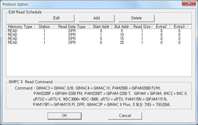 |
| <Figure 2> Example of GMPC II communication driver’s Option dialogue box |
You can set read schedule by using ![]() ,
, ![]() ,
, ![]() button and listbox of <Figure
2>.
button and listbox of <Figure
2>.
 |
| <Figure 3> Example of GMPC II communication driver’s read schedule Add/Edit dialogue box |
When you click Add button or Edit button in dialogue box of <Figure 2>, dialogue box of <Figure 3> is shown.
You can write DPR equipment's setting value by using write settings.
Digital Write
GMPC II communication driver for DPR model don't support digital write.
Analog Write
Analog write setting parameters are as follows:
1) PORT Port no. (0 ~ 255)
2) STATION DPR controller station number = 0 ~ 255.
3) ADDRESS Setting data type = refer to <Table 3>.
4) Extra1 Model name = DPR.
5) Extra2 Setting content = 0 ~ 5 or 255. ( refer to <Table 3> )
Note) Analog write for DPR equipment send write command to GMPC controller after reading the corresponding setting address(data).
Extra2 |
Contents |
Output data format |
Address |
0 |
OCR Setting |
BYTE, WORD |
0 : Ground fault function on/off (1 = on, 0 = off) 1 : OCR, OCGR Instantaneous element Lock(1 or 0) 2 : Time delay current(x 10) 3 : Instantaneous current(x 10) 4 : Inverse Time operation hour(x 100) 5 : Definite Time operation hour(x 10) 6 : Characteristic curve |
1 |
OCGR Setting |
||
2 |
SGR Setting |
BYTE, WORD |
0 : Operating voltage 1 : Operatin current(x 10) 2 : Operating time(x 10) 3 : Relay characteristic angle |
3 |
OVR(UVR) Setting |
BYTE, WORD |
0 : OVR/UVR function selection 1 : OVR operating voltage 2 : UVR operating voltage 3 : OVR operating time(x 100) 4 : UVR operating time(x 100) 5 : Zero voltage LOCK |
4 |
OVR/UVR Setting |
BYTE, WORD |
0 : - 1 : OVR operating voltage 2 : UVR operating voltage 3 : OVR operating time(x 100) 4 : UVR operating time(x 100) 5 : Zero voltage LOCK |
5 |
OVGR Setting |
BYTE, WORD |
0 : Instantaneous element LOCK 1 : Time delay operating voltage 2 : Instantaneous operating voltage 3 : Inverse Time operating time(x 100) 4 : Definite Time operating time(x 10) 5 : Characteristic curve |
255 |
Remote Reset |
Don't care |
Don't care |
| <Table 3> Setting element and data range for Analog write | |||
Write example 1)
PORT : 0 Station : 1, ADDRESS : 00000, EXTRA1 : DPR, EXTRA2 : 0
The setting parameter shown above is ground fault function on/off control example for OCR setting.
Write example 2)
PORT : 0 Station : 1, ADDRESS : 00003, EXTRA1 : DPR, EXTRA2 : 0
The setting parameter shown above is OVR operating time setting example for OCR setting.
Write example 3)
PORT : 0 Station : 1, ADDRESS : 00002, EXTRA1 : DPR, EXTRA2 : 2
The setting parameter shown above is operating time setting example for SGR setting.
Write example 4)
PORT : 0 Station : 1, ADDRESS : 00000, EXTRA1 : DPR, EXTRA2 : 255
The setting parameter shown above is remote reset control example to 1 DPR controller station number.
Connection of main power and communication cable are as follows.
Connection of main power
Please connect 110 ~ 125V DC main power to 3(+), 5(-) connector at DPR controller's rear panel such as <Figure 4>.
<Figure 5> is appearance of DPR controller.
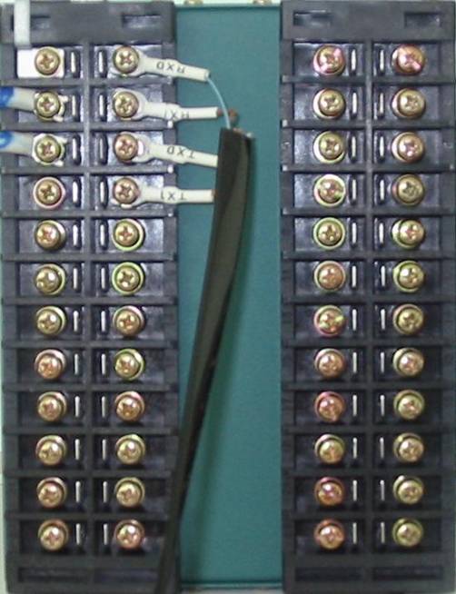 |
| <Figure 4> Connection example of main power and communication cable to DPR controller |
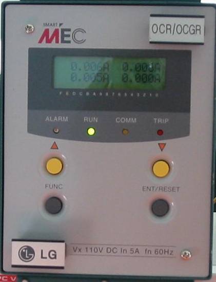 |
| <Figure 5> Appearance of DPR controller |
Connection of I-NET communication cable
Please connect I-NET RS-485 communication cable to 2( Tx0 ), 4( Tx1 ), 6( Rx0 ), 8( Rx1 ) connector such as <Figure 4>.
Note) When you connect DPR and GMPC, you have to connect Rx = Tx, Tx = Rx respectively. ( I-NET cable = offered by LSIS Co., Ltd. when you buying GMPC or DPR )
Connection of GMPC V almost equal with GMPC III. So you can refer to connection of GMPC III part.
<Figure 6> is apperance of GMPC V controller.
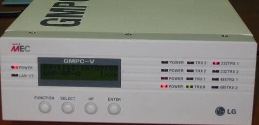 |
| <Figure 6> Apperance of GMPCV controller |
Note) Password input method : you can input 'password' by using 4 button of frong panel. ( Inital(default) Password : press 'FUNCTION', 'SELECT', 'UP', 'ENTER' button 2 times by turns )
Setting of GMPC V)
1. Time & Date : Date and Time setting of GMPC V.
2. Model : Model, protocol and communication method of GMPC V.
Model | Protocol : select GMP(I-NET protocol of GMPC) or MODBUS protocol,
Model | Media : select communication media of GMPC V.
Model | Main Port : select Primary(P) or Secondary(S).
3. Serial : select Com1 or Com2 port of GMPC V.
4. Network(This) : select LAN1, LAN2 Ethernet port.
Network(This) | Ethernet Port : select primary ethernet port of GMPC V.
Network(This) | IP_0 : input IP Address of Primary Ethernet,
Network(This) | Port_0 No_0 : input Port number of Primary Ethernet,
Network(This) | Netmask_0 : input Subnet mask of Primary Ethernet,
Network(This) | Gateway_0 : input Gateway IP Address of Primary Ethernet,
Network(This) | Host_IP0 : input Host(PC, etc) IP Address of Primary Ethernet.
After setting GMPC V controller, save the setting by using 'ENTER' button.
Also, you have to reset(power off and power on) in order to apply the setting value. (don't reset, GMPC V use the old setting value)
Note) When you using the 'Ethernet' communication, you have to set Host(PC, etc) IP address at GMPC V controller.
Also if you don't use gateway at network, please set 'Gateway' IP address to '0.0.0.0'.
Note) You must input power for the first time of GIPAM-2200, etc, and input power GMPC V.
If you input power GMPC V the first and input GIPAM-2200, etc, GMPC V can't find connected equipment. So it may not be able to communicate with connected equipment.