GLa MD1000 communication driver is the driver to communicate with controller of GLa electronica in Korea.
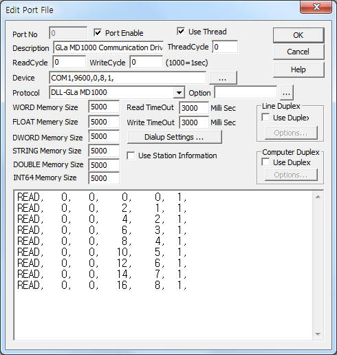
<Figure 1> is read setting example of GLa MD1000 communication driver.
 |
| <Figure 1> Read setting example of GLa MD1000 communication driver |
Device part of <Figure 1> input Com Port(COM1), Baud Rate(9600), Parity Bit(0), Data Bit(8), Stop Bit(1) respectively according to setting of controller.
Note) MD1000, MD100R, MD1010, MD1010R model can use GLa MD1000 communication driver.
GLa MD1000 communication driver read schedule
Read schedule setting parameters are as follows:
1) STATION – Controller station number = 0 ~ 99.
2) Read command – Don't care.
3) Read start address – Read address. ( Refer to <Table 1> )
4) Save Start Address for Communication Server – saveing start address of Communication Server.
5) Read Size – Fixed to 1.
Read schedule example)
READ, 0, 0, 0, 0, 1,
READ, 0, 0, 2, 1, 1,
READ, 0, 0, 4, 2, 1,
READ, 0, 0, 6, 3, 1,
READ, 0, 0, 8, 4, 1,
READ, 0, 0, 10, 5, 1,
READ, 0, 0, 12, 6, 1,
READ, 0, 0, 14, 7, 1,
READ, 0, 0, 16, 8, 1,
<Table 1> is read address and parameter content of GLa MD1000 communication driver.
Parameter content |
Read Address |
Display reading |
0000 |
Main Scale |
0002 |
2nd scale |
0004 |
Peak N1 |
0006 |
Peak N2 |
0008 |
Tare value |
0010 |
Net value |
0012 |
Input value before linearization |
0014 |
Cold junction temperature |
0016 |
| <Table 1> Read address and parameter content of GLa MD1000 communication driver | |
Please refer to 31 page of Gla MD1000 User Manual for more read address and parameter contents.
You can control MD series controller by using write settings.
Digital Write
Digital write setting parameters are as follows:
1) PORT Port no. (0 ~ 255)
2) STATION Controller station number = 0 ~ 99.
3) ADDRESS Write address. ( Refer to <Table 1> )
4) Extra1 Don't care.
5) Extra2 Don't care.
Write example 1)
PORT : 0, STATION:0, ADDRESS : 0323, Extra1 : , Extra2 :
The setting parameter shown above is a Enable of Alarm Output Control example for 0 station number of MD series controller.
Analog Write
Analog write setting parameters are as follows:
1) PORT Port no. (0 ~ 255)
2) STATION Controller station number = 0 ~ 99.
3) ADDRESS Write address. ( Refer to <Table 1> )
4) Extra1 Output data format : 0 = interger, 1 ~ 4 = 1 ~ 4 decimal point.
5) Extra2 Don't care.
Write example 1)
PORT : 0, STATION:0, ADDRESS : 0221, Extra1 : 0, Extra2 :
The setting parameter shown above is an example of Input type changing for 0 station number of MD series controller.