GMPC II communication driver is the driver to communicate with power meter GIMAC/GIMACII/GIMACIII model of LSIS Co., Ltd. in Korea.
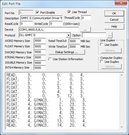
<Figure 1> is read setting example of GMPC II communication driver for GIMAC model.
|
|
| <Figure 1> Read setting example of GMPC II communication driver for GIMAC model |
Device part of <Figure 1> input Com Port(COM1), Baud Rate(9600), Parity Bit(0), Data Bit(8), Stop Bit(1) respectively according to setting of GMPC.
Baud rate, parity bit, data bit, stop bit can set by using switch of rear panel(GMPC controller).
GMPC II communication driver read schedule for GIMAC/GIMACII/GIMACIII
Read schedule setting parameters are as follows:
1) STATION – GIMAC controller station number = 0 ~ 255.
2) Controller Model – Model = GIMAC3 – GIMACIII, blank, etc - GIMAC, GIMACII.
3) Read data type – Data type = 0, 1, 2, 3, 4, 5....
4) Save Start Address for Communication Server – saveing start address of Communication Server.
5) Read Size – Read size. Fixed according to read data type. ( Refer to <Table 1>, <Table 2> )
Read schedule example)
READ, 3, 0, 0, 0, 4,
FLOAT, 3, 0, 1, 0, 3,
FLOAT, 3, 0, 2, 3, 3,
FLOAT, 3, 0, 3, 6, 3,
FLOAT, 3, 0, 4, 9, 3,
FLOAT, 3, 0, 5, 12, 3,
FLOAT, 4, GIMAC3, 1, 20, 3,
FLOAT, 4, GIMAC3, 2, 23, 3,
FLOAT, 4, GIMAC3, 3, 26, 3,
FLOAT, 4, GIMAC3, 4, 29, 3,
FLOAT, 4, GIMAC3, 5, 32, 3,
READ, 4, GIMAC3, 13, 10, 4,
READ, 4, GIMAC3, 14, 20, 4,
Note) You must select “I-NET G-2 Version” when using th GIMAC II-Plus model.
<Table 1> is read data type and contents for GIMAC, GIMAC II model.
<Table 2> is read data type and contents for GIMAC III model.
| Read Data Type | Contents | Data Unit | Data Size | Remarks |
0 |
Status of controller |
WORD |
4 |
Refer to <Table 3> |
1 |
IR,IS,IT |
FLOAT |
3 |
|
2 |
VRS,VST,VRT |
|||
3 |
PF,W,VAR |
|||
4 |
FREQ,WH,VARH |
|||
5 |
VRN,VSN,VTN |
|||
| <Table 1> Read data type and contents for GIMAC, GIMAC II model | ||||
| Read Data Type | Contents | Data Unit | Data Size | Remarks |
1 |
IR,IS,IT |
FLOAT |
3 |
|
2 |
VRS,VST,VRT |
|||
3 |
PF,W,VAR |
|||
4 |
FREQ,WH,VARH |
|||
5 |
VRN,VSN,VTN |
|||
7 |
Reverse Power, Reverse Energy,
|
|||
8 |
|
|||
13 |
Setting value 1 |
BYTE, WORD |
10 |
Refer to <Table 4> |
14 |
Setting value 2 |
WORD, FLOAT |
4 |
Refer to <Table 5> |
20 |
Device information 1 |
WORD |
5 |
Refer to <Table 6> |
21 |
Device information 2 |
BYTE |
13 |
Unique name 1 |
22 |
Device information 3 |
BYTE |
13 |
Unique name 2 |
23 |
Device information 4 |
BYTE |
13 |
Refer to <Table 7> |
| <Table 2> Read data type and contents for GIMAC III model | ||||
Data Saving Address |
Bit position | Contents | Remarks |
Start Add + 0 |
7 |
Output of heavy fault |
Current fault input status (LATCH) |
6 |
Output of light fault |
||
5 |
OVGR input of heavy fault |
||
4 |
OCGR input of heavy fault |
||
3 |
OVR input of heavy fault |
||
2 |
UVR input of heavy fault |
||
1 |
SGR input of heavy fault |
||
0 |
OCR input of heavy fault |
||
Start Add + 1 |
7 |
Output of heavy fault |
Current fault input status (Pulse) |
6 |
Output of light fault |
||
5 |
OVGR input of heavy fault |
||
4 |
OCGR input of heavy fault |
||
3 |
OVR input of heavy fault |
||
2 |
UVR input of heavy fault |
||
1 |
SGR input of heavy fault |
||
0 |
OCR input of heavy fault |
||
Start Add + 2 |
7 ~ 5 |
Don't care |
CB status |
4 |
CB ON output status |
||
3 |
CB OFF output status |
||
2 |
0 = LOCAL, 1 = REMOTE |
||
1 |
CB ON input status |
||
0 |
CB OFF input status |
||
Start Add + 3 |
7 ~ 4 |
Don't care |
RESET status |
3 |
REMOTE FAULT RESET |
||
2 |
LOCALFAULT RESET |
||
1 |
REMOTE WH RESET |
||
0 |
LOCAL WH RESET |
||
| <Table 3> Data saving address and contents of '0' read data type for GIMAC, GIMAC II (Data of 4 byte) | |||
| Data Saving Address | Contents |
Rnage |
Remarks |
| 0 | Setting id |
01h (Fixed) |
BYTE |
| 1 | Setting id |
0Ah (Fixed) |
|
| 2 | Line Parameter |
1 ~ 6 |
|
| 3 | Power quantity selection to be using output pulse |
1 or 2 |
|
| 4 | Unit setting of power |
1 ~ 3 |
|
| 5 | Data communication Enable/Disable |
1 or 2 |
|
| 6 | Power Demand Period |
1 ~ 60 |
|
| 7 | Ampere Demand 1 Period |
10 ~ 3600 |
WORD |
| 8 | Ampere Demand 2 Period |
||
| 9 | Ampere Demand 3 Period |
||
| <Table 4> Data saving address and contents of '13'(setting value 1) read data type for GIMAC III | |||
Data Saving Address |
Contents |
Rnage |
Data size |
0 |
CT ratio |
1 ~ 30000 |
WORD |
1 |
Setting value of pulse output |
||
2 |
PT ratio |
1.0 ~ 30000.0 |
FLOAT |
3 |
Reservd |
|
WORD |
| <Table 5> Data saving address and contents of '14'(setting value 2) read data type for GIMAC III | |||
Data Saving Address |
Contents |
Data size |
0 |
Setting id |
WORD |
1 |
Program Version Number |
|
2 |
Digital In |
|
3 |
Digital Out |
|
4 |
Reserved |
|
| <Table 6> Data saving address and contents of '20'(device information 1) read data type for GIMAC III | ||
Data Saving Address |
Contents |
Data size |
0 ~ 3 |
Reserved |
BYTE |
4 ~ 7 |
E2_para1 ~ 4 |
|
8 |
Time Sync 지원 |
|
9 |
Report 지원 |
|
10 ~ 12 |
Reserved |
|
| <Table 6> Data saving address and contents of '23'(device information 4) read data type for GIMAC III | ||
You can control GIMAC equipment by using write settings.
Note) You can write when the GIMAC controller setting is 'REMOTE'. (Inportant: If you want to write 'Remote CB', you have to connect 'Remote CB ON/OFF' wiring.)
Digital Write
Digital write setting parameters are as follows:
1) PORT Port no. (0 ~ 255)
2) STATION GIMAC controller station number = 0 ~ 255.
3) ADDRESS Control type.
EXTRA1 = space , ... (GIMAC model) .
0000 - CB ON.
0001 - CB OFF.
0002 - FAULT RESET.
0003 - WH CLEAR.
0004 - VARH CLEAR.
0005 - HISTORY CLEAR.
0006 - CB ON 횟수 CLEAR.
0007 - CB ON Time Clear.
0008 - Vo MAX Clear.
0009 - All Back Up Data Clear.
EXTRA1 = GIMAC2. (CB control : Extra1 = CB, CBON, CBOFF)
0042 – WH/VARH Reset.
0043 – Fault Reset.
0045 – Reset of CB control count.
0046 – Reset of CB sending an electric current time.
EXTRA1 = GIMAC3.
0003 – Active Energy Reset.
0004 – Reactive Energy Reset.
000A – Reverse Energy Reset.
000B – Power Demand Reset.
000C – Ampere Demand 1 Peak Reset.
000D - Ampere Demand 2 Peak Reset.
000E - Ampere Demand 3 Peak Reset.
000F – System Reset.
EXTRA1 = CB, CBON, CBOFF - Don't care.
4) Extra1 GIMAC model or CB ON/OFF command.
5) Extra2 Don't care.
Note) You can control CB ON, CB OFF, etc when the GIMAC controller setting is 'REMOTE'.
Write example 1)
PORT : 0 Station : 1, ADDRESS : 0000, EXTRA1 : CB, EXTRA2 : 0
The setting parameter shown above is a CB ON/OFF control example for 1 station number of GIMAC controller.
Write example 2)
PORT : 0 Station : 1, ADDRESS : 0000, EXTRA1 : CBON, EXTRA2 : 0
The setting parameter shown above is a CB ON control example for 1 station number of GIMAC II controller.
Write example 3)
PORT : 0 Station : 1, ADDRESS : 0000, EXTRA1 : CBOFF, EXTRA2 : 0
The setting parameter shown above is a CB OFF control example for 1 station number of GIMAC II controller.
Write example 4)
PORT : 0 Station : 1, ADDRESS : 0000F EXTRA1 : GIMAC3, EXTRA2 : 0
The setting parameter shown above is a systen reset example for 1 station number of GIMAC III controller.
Write example 5)
PORT : 0 Station : 1, ADDRESS : 0003, EXTRA1 : GIMAC3, EXTRA2 : 0
The setting parameter shown above is an Active Energy reset example for 1 station number of GIMAC III controller.
Write example 6)
PORT : 0 Station : 1, ADDRESS : 0000, EXTRA1 : , EXTRA2 : 0
The setting parameter shown above is a CB ON control example for 1 station number of GIMAC controller.
Write example 7)
PORT : 0 Station : 2, ADDRESS : 0002, EXTRA1 : , EXTRA2 : 0
The setting parameter shown above is a fault reset example for 2 station number of GIMAC controller.
Analog Write
Analog write setting parameters are as follows:
1) PORT Port no. (0 ~ 255)
2) STATION GIMAC controller station number = 0 ~ 255.
3) ADDRESS Setting data type. ( Refer to <Table 8>, <Table 9> )
4) Extra1 GIMAC model.
GIMAC3 – GIMACIII,
space, .. - Don't care.
5) Extra2 0 or 1 when Extra1 = GIMAC3.
0 - setting 1. (Refer to <Table 8>)
1 - setting 2. (Refer to <Table 9>)
Address range (Setting data type) |
Contents |
Output range |
0 |
Line Parameter |
1 ~ 6 |
1 |
Power quantity selection to be using output pulse |
1 or 2 |
2 |
Unit setting of power |
1 ~ 3 |
3 |
Setting of data communication Enable/Disable |
1 or 2 |
4 |
Power Demand Period |
1 ~ 60 |
5 |
Ampere Demand 1 Period |
10 ~ 3600 |
6 |
Ampere Demand 2 Period |
|
7 |
Ampere Demand 3 Period |
|
| <Table 8> Setting parameters when Extra2 setting value is '0'(setting 1) | ||
Address range (Setting data type) |
Contents |
Output range |
0 |
Setting of CT ratio |
1 ~ 30000 |
1 |
Setting of pulse output ratio |
|
2 |
Setting of PT ratio |
1.0 ~ 30000.0 |
3 |
Reservd |
|
| <Table 9> Setting parameters when Extra2 setting value is '1'(setting 2) | ||
Write example 1)
PORT : 0 Station : 0, ADDRESS : 00002 EXTRA1 : GIMAC3, EXTRA2 : 0, Output value = 2
The setting parameter shown above is power unit setting(value = 2) example for 0 station number of GIMAC III controller.
Write example 2)
PORT : 0 Station : 0, ADDRESS : 0000, EXTRA1 : GIMAC3, EXTRA2 : 1, Output value = 10.0
The setting parameter shown above is CT ratio setting(value = 10) example for 0 station number of GIMAC III controller.
Write example 3)
PORT : 0 Station : 0, ADDRESS : 0002, EXTRA1 : GIMAC3, EXTRA2 : 1, Output value = 2.1
The setting parameter shown above is PT ratio setting(value = 2.1) example for 0 station number of GIMAC III controller.