GE TLC communication driver is the driver to communicate with Total Lighting Controller of GE in U.S.A.
Reference) RLINK, DLL-RLINK communication driver
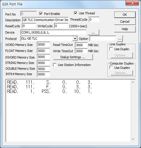
<Figure 1> is read setting example of GE TLC communication driver.
 |
| <Figure 1> Read setting example of GE TLC communication driver |
Device part of <Figure 1> input Com Port(COM1), Baud Rate(19200), Parity Bit(0), Data Bit(8), Stop Bit(1) respectively according to setting of controller.
GE TLC communication driver read schedule
Read schedule setting parameters are as follows:
1) STATION – Controller station number or panel number.
S, F read command = 0 ~ 999 station number,
PSS read command = 0 ~ 999 panel number.
2) Read command – Command = S(default) - read of relay On/Off status, F - read of each relay fail status, PSS - read of PSS status.
3) Read start addresst – Don't care.
4) Save Start Address for Communication Server – saveing start address of Communication Server.
5) Read Size – Read size. S, F = fixed to 3, PSS = fixed to 1.
Read schedule example)
READ, 111, S, 0, 0, 3,
READ, 111, F, 0, 3, 3,
READ, 1, PSS, 0, 10, 1,
You can control the lighting controller by using write settings.
Digital Write
Digital write setting parameters are as follows:
1) PORT Port no. (0 ~ 255)
2) STATION Controller station number or panel number.
S write command = 0 ~ 999 station number,
PSS write command = 0 ~ 999 panel number.
3) ADDRESS Writing channel number or PSS switch number.
S write command = 0000 ~ 002F,
ex) 001A - 27th bit of RLINK,
PSS write command = 0000 ~ 000F.
4) Extra1 Write command = S or blank, etc - write of relay On/Off status, PSS - write of PSS status.
5) Extra2 Don't care.
<Table 1> is address of RLINK(GE TLC) and GE TLC communication driver.
RLINK |
AutoBase |
RLINK |
AutoBase |
RLINK |
AutoBase |
1 |
0000 |
17 |
0010 |
33 |
0020 |
2 |
0001 |
18 |
0011 |
34 |
0021 |
3 |
0002 |
19 |
0012 |
35 |
0022 |
4 |
0003 |
20 |
0013 |
36 |
0023 |
5 |
0004 |
21 |
0014 |
37 |
0024 |
6 |
0005 |
22 |
0015 |
38 |
0025 |
7 |
0006 |
23 |
0016 |
39 |
0026 |
8 |
0007 |
24 |
0017 |
40 |
0027 |
9 |
0008 |
25 |
0018 |
41 |
0028 |
10 |
0009 |
26 |
0019 |
42 |
0029 |
11 |
000A |
27 |
001A |
43 |
002A |
12 |
000B |
28 |
001B |
44 |
002B |
13 |
000C |
29 |
001C |
45 |
002C |
14 |
000D |
30 |
001D |
46 |
002D |
15 |
000E |
31 |
001E |
47 |
002E |
16 |
000F |
32 |
001F |
48 |
002F |
| <Table 1> Address of RLINK(GE TLC) and GE TLC communication driver | |||||
Write example 1)
Port : 0 Station : 18 Address : 0003 Extra1 : , EXTRA2 :
The setting parameter shown above is a relay control( ON/OFF ) example for 4th channel of RLINK.
Write example 2)
Port : 0 Station : 1 Address : 0002 Extra1 : PSS , EXTRA2 :
The setting parameter shown above is all relay control( ON/OFF ) example for 3rd switch number at 1 PSS pannel number:
Analog Write
GE TLC communication driver don't support analog write.