GE-SNP communication driver is the driver to communicate(loader port) with PLC of GE Fanuc Automation in U.S.A.
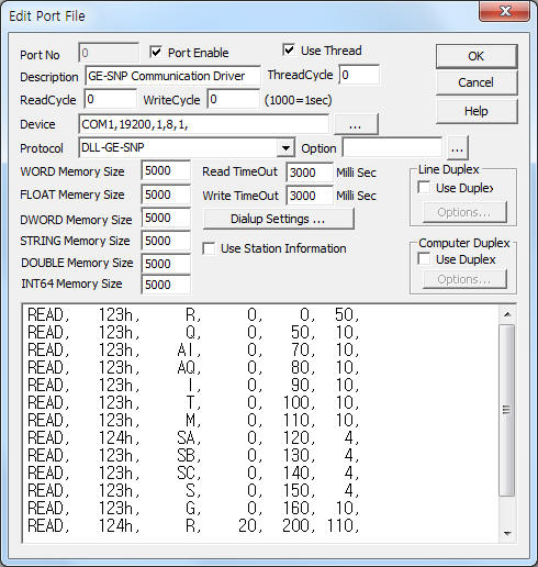
<Figure 1> is read setting example of GE-SNP communication driver.
 |
| <Figure 1> Read setting example of GE-SNP communication driver |
Device part of <Figure 1> input Com Port(COM1), Baud Rate(19200), Parity Bit(1), Data Bit(8), Stop Bit(1) respectively according to setting of PLC.
GE-SNP communication driver read schedule
Read schedule setting parameters are as follows:
1) STATION – SNP protocol station number of PLC = 0 ~ 65535. ( you can use 0 SNP station number when communicating(serial) with a single PLC )
2) Read command – Memory type of PLC = R, AI, AQ, I, Q, T, M, SA, SB, SC, S, G.
3) Read start addresst – Read start address of PLC memory.
4) Save Start Address for Communication Server – saveing start address of Communication Server.
5) Read Size – Read size of word unit. Word unit memory area = 1 ~ 110, bit unit memory area = 1 ~ 220.
6) Data saving method - Data saving method when byte memory area, 0 = save readed data 'byte' unit, 1 = save readed data '10 bit' unit(arrange by 10 bit unit).
Note) GE-SNP communication driver support 0 ~ 65535(0h ~ FFFFh) SNP(CPUT) station number.
Read schedule example)
READ, 123h, R, 0, 0, 50,
READ, 123h, Q, 0, 50, 10,
READ, 123h, AI, 0, 70, 10,
READ, 123h, AQ, 0, 80, 10,
READ, 123h, I, 0, 90, 10,
READ, 123h, T, 0, 100, 10,
READ, 123h, M, 0, 110, 10,
READ, 124h, SA, 0, 120, 4,
READ, 123h, SB, 0, 130, 4,
READ, 123h, SC, 0, 140, 4,
READ, 123h, S, 0, 150, 4,
READ, 123h, G, 0, 160, 10,
READ, 124h, R, 20, 200, 110,
READ, 124h, M, 50, 310, 10, 1, 0,
<Table 1> is memory area and contents of GE PLC.
Memory area |
Contents |
Data unit |
R |
Register area |
WORD |
AI |
Analog input |
|
AQ |
Analog output |
|
I |
Digital input |
BYTE, BIT |
Q |
Digital output |
|
T |
Discrete Temporaries |
|
M |
Discrete Internals |
|
SA, SB, SC |
Discretes |
|
S |
Discretes |
|
G |
Genus Global Data |
|
| <Table 1> Memory area and contents of GE PLC | ||
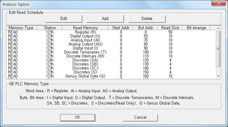
If you click the icon ![]() in protocol option part, you
can see the dialogue box such as <Figure 2>. you can also set read schedule by
using this part.
in protocol option part, you
can see the dialogue box such as <Figure 2>. you can also set read schedule by
using this part.
 |
| <Figure 2> Example of GE-SNP communication driverí»s Option dialogue box |
You can set read schedule by using ![]() ,
, ![]() ,
, ![]() button and listbox of <Figure
2>.
button and listbox of <Figure
2>.
 |
| <Figure 3> Example of GE-SNP communication driverí»s read schedule Add/Edit dialogue box |
When you click Add button or Edit button in dialogue box of <Figure 2>, dialogue box of <Figure 3> is shown.
You can write memory value of PLC by using write settings.
Digital Write
Digital write setting parameters are as follows:
1) PORT Port no. (0 ~ 255)
2) STATION SNP protocol station number of PLC = 0 ~ 65535. ( you can use 0 SNP station number when communicating(serial) with a single PLC )
3) ADDRESS Bit unit address in memory area.(decimal)
4) Extra1 Write memory area = I, Q, T, M, SA, SB, SC, G. ( only bit unit memory )
5) Extra2 Don't care.
Write example 1)
Port : 0 Station : 291 Address : 0001 Extra1 : Q, EXTRA2 :
The setting parameter shown above is bit write( ON/OFF ) example for 0001(1st) bit of Q memory area at 291 SNP station number.
Write example 2)
Port : 0 Station : 291 Address : 0021 Extra1 : M, EXTRA2 :
The setting parameter shown above is bit write( ON/OFF ) example for 0021(21th) bit of M memory area at 291 SNP station number.
Analog Write
Analog write setting parameters are as follows:
1) PORT Port no. (0 ~ 255)
2) STATION SNP protocol station number of PLC = 0 ~ 65535. ( you can use 0 SNP station number when communicating(serial) with a single PLC )
3) ADDRESS Word/byte unit address in memory area.(decimal)
4) Extra1 Write memory area = word unit memory area : R, AI, AQ, byte unit memory area : I, Q, T, M, SA, SB, SC, G.
5) Extra2 Don't care.
Write example 1)
Port : 0 Station : 291 Address : 0007 Extra1 : AQ, EXTRA2 :
The setting parameter shown above is word unit analog write example for 0007(7th) word of AQ memory area at 291 SNP station number.
Write example 2)
Port : 0 Station : 291 Address : 0123 Extra1 : R, EXTRA2 :
The setting parameter shown above is word unit analog write example for 0123(123th) word of R memory area at 291 SNP station number.
Write example 3)
Port : 0 Station : 291 Address : 0012 Extra1 : M, EXTRA2 :
The setting parameter shown above is byte unit analog write example for 0012(12th) byte of M memory area at 291 SNP station number.
Connection of communication cable when Varsa Max GE PLC model are as follows.
Connection of RS-232C communication cable
Please connect normal RS-232C serial communication cable to 9pin connector such as <Figure 4>.
Connection of RS-422/485 communication cable
Please connect 10 ( Rx- ), 11 ( Rx+ ), 12 ( Tx- ), 13 ( Tx+ ) of 15 pin RS-422/485 connector and Tx-, Tx+, Rx-, Rx+ connector of computer respectively. ( Refer to <Figure 4> )
15 pin connector of VersaMax GE PLC computer( RS-485 )
10 pin( Rx-) ---------------------------- Tx-
11 pin( Rx+) ---------------------------- Tx+
12 pin( Tx-) ---------------------------- Rx-
13 pin( Tx+) ---------------------------- Rx+
 |
| <Figure 4> Connection example of communication cable and main power to Versa Max model og GE PLC |
SNP station number(ID) can set by using Versa Pro program of GE Fanuc Automation.
Setting method of SNP station number are as follows.
1) Run Versa Pro ladder program and open project or create new project.
2) Please select(double click of mouse left button) 'Hardware Configuration' of Folder Browser window.
Then open 'HWC setting window' such as <Figure 5>.
3) When you select í«Edit|Rack Operations|Configure CPU Parametersí» at HWC setting window(<Figure 5>).
Then will be opened 'CPU Parameters setting window' such as <Figure 6>.
4) Please select 'Port1( RS-232C )' or 'Port2( RS-485 )' tap at <Figure 6>.
5) Click 'SNP ID' and select(double click of mouse left button) this menu.
Then will be opened 'SNP ID input dialog' such as <Figure 7>.
6) Input SNP ID(station number) at <Figure 7> dialog.
SNP ID input range = max 6 ~ 7 digit hexadecimal unit.
But available SNP ID for GE-SNP communication driver = 0h ~ FFFFh(4 digit, 65535).
7) Download(store) th Hardware Configuration data to PLC by using Versa Pro Ladder program.
 |
| <Figure 5> Example of HWC window |
 |
| <Figure 6> Example of CPU Parameter setting window |
 |
| <Figure 7> Example of SNP ID input dialog |