FUJI MICREX-SX Loader ENET/Serial communication driver is the driver to communicate with MICREX-SX PLC Loader port of Fuji Electric Co., Ltd. in Japan.
FUJI MICREX-SX Loader ENET/Serial communication driver have 2 type of interface, Ethernet and Serial of RS-232C.
Ethernet : connect to RJ45 ( LAN ) Ethernet communication module(NP1L-ET1, ...).
RS-232C Serial : connect to Loader port of CPU unit.
Note) Normally FUJI MICREX-SX Ethernet communication module support 8 ~ 9 connection each service port. (2 service port support )
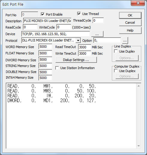
<Figure 1> is read setting example of FUJI MICREX-SX Loader ENET/Serial communication driver.
 |
| <Figure 1> Read setting example of FUJI MICREX-SX Loader ENET/Serial communication driver |
Device part of <Figure 1> input Device type(TCP/IP), IP address of PLC(192.168.123.50), service port of TCP/IP protocol (502, refer to chapter 4 ),respectively, according to setting of PLC.
When you use the Serial communication with Loader port of PLC, Device part can set such as 'COM1, 38400,0,8,1' according to setting of PLC.
Also you can input 'protocol type' (1 : serial, 0 : ethernet, default = 0) by using option part.
Note) You must be set to the same protocol type and communication device.
FUJI MICREX-SX Loader ENET/Serial communication driver read schedule
Read schedule setting parameters are as follows:
1) STATION – Bus station = 0 ~ 512.
0 : CPU 0, ( default CPU )
1 ~ 7 : CPU1 ~ CPU7 Local CPU,
1+256 ~ 7 + 256 : CPU1 ~ CPU7 Remote CPU,
8 ~ 255 : P/PE-link or FL-Net Local Module,
8+256 ~ 255 + 256 : CPU1 ~ P/PE-link or FL-Net Remote Module.
2) Read command – Read memory type or command = IW, ID, QW, QD, MW1, MW3, MW10, MD1, MD3, MD10, etc. ( Refer to <Table 1> )
3) Read start address – Word(equal Word/Dword memory type) unit read start address in memory type = 0 ~ .
4) Save Start Address for Communication Server – saveing start address of Communication Server.
5) Read Size – Read size of Word, Dword unit = Word 1 ~ 254, Dword : 1 ~ 127. ( difference accordign to PLC module )
Read schedule example)
READ, 0, MW1, 0, 0, 50,
READ, 0, MW3, 0, 50, 100,
READ, 0, IW, 0, 200, 20,
DWORD, 0, MD1, 200, 0, 127,
<Table 1> is read/write command and contents of FUJI MICREX-SX LOADER ENET/SERIAL communication driver.
| Read/Write command | Contents | Remarks |
| MW1, MD1, MX1(when digital write) | Standard Memory ( Non Retain Memory) | All memory value = 0, when CPU Reset( Power reset etc ) |
| MW3, MD3, MX3(when digital write) | Retain Memory | |
| MW10, MD10, MX10(when digital write) | System Memory | |
| IW, ID, QW, QD, QX(when digital write) | Input, Output Memory | I, Q = equal memory according to Address = I (input), Q (output) |
| MW1.1, MD1.1, MX1.1(when digital write) | P/PE-link Standard Memory | When using P/PE-link or FL-Net Module |
| MW3.1, MD3.1, MX3.1(when digital write) | P/PE-link Retain Memory | |
| MW10.1, MD10.1, MX10.1(when digital write) | P/PE-link System Memory | |
| IW.1, ID.1, QW.1, QD.1, QX.1(when digital write) | P/PE-link Input, Output Memory | |
| MW1.2, MD1.2, , MX1.2(when digital write) | FL-Net Standard Memory | |
| MW3.2, MD3.2, MX3.2(when digital write) | FL-Net Retain Memory | |
| MW10.2, MD10.2, MX10.2(when digital write) | FL-Net System Memory | |
| IW.2, ID.2, QW.2, QD.2, QX.2(when digital write) | FL-Net Input, Output Memory | |
| <Table 1> Read/write command and contents of FUJI MICREX-SX LOADER ENET/SERIAL communication driver | ||
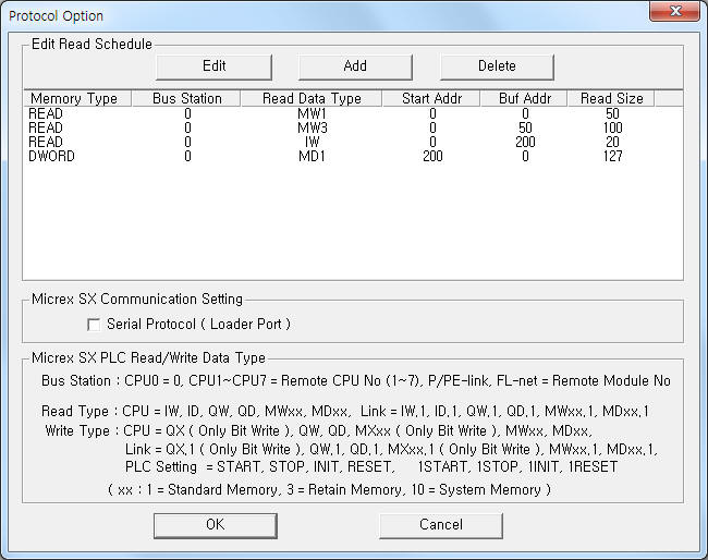
If you click the icon ![]() in protocol option part, you
can see the dialogue box such as <Figure 2>. you can also set read schedule by
using this part.
in protocol option part, you
can see the dialogue box such as <Figure 2>. you can also set read schedule by
using this part.
 |
| <Figure 2> Example of FUJI MICREX-SX LOADER ENET/SERIAL communication driver¡¯s Option dialogue box |
You can set read schedule by using ![]() ,
, ![]() ,
, ![]() button and listbox of <Figure
2>.
button and listbox of <Figure
2>.
Also you can set Protocol type at the part of ¡®Serial Protocol ( Loader Port )¡¯ shown in <Figure 2>.( don't check : Ethernet, check : Serial )
 |
| <Figure 3> Example of FUJI MICREX-SX LOADER ENET/SERIAL communication driver¡¯s read schedule Add/Edit dialogue box |
When you click Add button or Edit button in dialogue box of <Figure 2>, dialogue box of <Figure 3> is shown.
You can change the value of device memory by using write settings.
Digital Write
Digital write setting parameters are as follows:
1) PORT Port no. (0 ~ 255)
2) STATION Bus station = 0 ~ 512.
0 : CPU 0, ( default CPU )
1 ~ 7 : CPU1 ~ CPU7 Local CPU,
1+256 ~ 7 + 256 : CPU1 ~ CPU7 Remote CPU,
8 ~ 255 : P/PE-link or FL-Net Local Module,
8+256 ~ 255 + 256 : CPU1 ~ P/PE-link or FL-Net Remote Module.
3) ADDRESS Write addres in memory type.
higher 3 ~ 7 digit = word unit address, lower 1 digit = 0 ~ F bit position.
4) Extra1 Write memory type or command = QX, QW, QD, MX1, MW1, MD1, MX3, MW3, MD3, MX10, MW10, DM10, etc. ( Refer to <Table 1> )
5) Extra2 Higher bit position when Dword unit device memory.
Dword device memory : 0 = 0h ~ Fh bit position, 1 = 10h ~ 1Fh bit position,
other device memory : don't care.
Write example 1)
PORT:0, station:0, ADDRESS:0057, Extra1: MX1, Extra2 :
The setting parameter shown above is a bit write(On/Off) example of 5 word, 7(8th) bit address, standard memory at default CPU(CPU0).
Write example 2)
PORT:0, station:0, ADDRESS:015F, Extra1: MX3, Extra2 :
The setting parameter shown above is a bit write(On/Off) example of 15 word, F(16th) bit address, retain memory at default CPU(CPU0).
Write example 3)
PORT:0, station:0, ADDRESS:0042, Extra1: QX, Extra2 :
The setting parameter shown above is a bit write(On/Off) example of 4 word, 2(3rd) bit address, input/output memory at default CPU(CPU0).
Write example 4)
PORT:0, station:0, ADDRESS:004E, Extra1: QX, Extra2 :
The setting parameter shown above is a bit write(On/Off) example of 4 word, E(15th) bit address, input/output memory at default CPU(CPU0).
Write example 5)
PORT:0, station:0, ADDRESS:1018A, Extra1: MW1, Extra2 :
The setting parameter shown above is a bit write(On/Off) example of 1018 word, A(10th) bit address, standard memory at default CPU(CPU0).
Write example 6)
PORT:0, station:0, ADDRESS:10183, Extra1: MD3, Extra2 : 0
The setting parameter shown above is a bit write(On/Off) example of 1018 word, 03(4th) bit address, standard memory at default CPU(CPU0).
Write example 7)
PORT:0, station:0, ADDRESS:10183, Extra1: MD3, Extra2 : 1
The setting parameter shown above is a bit write(On/Off) example of 1018 word, 13h(20th) bit address, standard memory at default CPU(CPU0).
Analog Write
Analog write setting parameters are as follows:
1) PORT Port no. (0 ~ 255)
2) STATION Bus station = 0 ~ 512.
0 : CPU 0, ( default CPU )
1 ~ 7 : CPU1 ~ CPU7 Local CPU,
1+256 ~ 7 + 256 : CPU1 ~ CPU7 Remote CPU,
8 ~ 255 : P/PE-link or FL-Net Local Module,
8+256 ~ 255 + 256 : CPU1 ~ P/PE-link or FL-Net Remote Module.
3) ADDRESS Decimal unit write addres in memory type.
4) Extra1 Write memory type or command = QW, QD, MW1, MD1, MW3, MD3, MW10, DM10, etc. ( Refer to <Table 1> )
5) Extra2 Don't care.
Write example 1)
PORT:0, station:0, ADDRESS:0007, Extra1: MW1, Extra2 :
The setting parameter shown above is a word write example of 7 word address, standard memory at default CPU(CPU0).
Write example 2)
PORT:0, station:0, ADDRESS:0015, Extra1: MW3, Extra2 :
The setting parameter shown above is a word write example of 15 word address, retain memory at default CPU(CPU0).
Write example 3)
PORT:0, station:0, ADDRESS:0032, Extra1: QW, Extra2 :
The setting parameter shown above is a word write example of 32 word address, input/output memory at default CPU(CPU0).
Write example 4)
PORT:0, station:0, ADDRESS:1000, Extra1: MD1, Extra2 :
The setting parameter shown above is a dword write example of 1000 word address, standard memory at default CPU(CPU0).
Write example 5)
PORT:0, station:0, ADDRESS:1055, Extra1: MD1, Extra2 :
The setting parameter shown above is a dword write example of 1055 word address, standard memory at default CPU(CPU0).
Connection of main power and communication cable are as follows.
Connection of main power
Please connect 100 ~ 120V AC or 200 ~ 240V AC 50/60HZ main power to L, N connector such as <Figure 4>.
<Figure 4> is connection example of main power and communication cable to FUJI MICREX-SX PLC.
 |
| <Figure 4> Connection example of main power and communication cable to FUJI MICREX-SX PLC |
Connection of Loader communication cable
Please connect Loader cable to loader port of MICREX-SX PLC's CPU module such as <Figure 4>.
Connection of Ethernet communication cable
Please connect Ethernet communication cable to RJ45 connector of NP1L-ET1, ... communication module such as <Figure 4>.
IP address and service can set by using D300WIN prgoram provided by FUJI Fuji Electric Co., Ltd.
1) Execute 'D300WIN' program and make new project or open a project.( Refer to <Figure 5> )
2) Open ¡®System Definition¡¯ menu. ( double click mouse left button etc )
3) Then appears ¡®System Definition¡¯ setting menu such as <Figure 6>.
4) Register all input, output, conmmunication, etc module and select Ethernet at <Figure 6>.
5) Select 'Properties' at Ethernet module menu(press mouse right button( Alt + Enter )), then appears dialog box such as <Figure 7>.
6) Input SX bus station no, etc at <Figure 7> and press ![]() button,
then appears dialog box such as <Figure 8>.
button,
then appears dialog box such as <Figure 8>.
7) Please input IP address at dialog box of <Figure 8>.
8) Select Detail Setting tap at <Figure 8> and select ¡®Self port standard No¡¯. ( Refer to <Figure 9> )
9) Input 0 ~ 65280 port number at <Figure 9>.
10) Service port number = ¡®Self port standard No.¡¯ + 251 and ¡®Self port standard No.¡¯ + 253.
example) When ¡®Self port standard No.¡¯ = 251, service port : 251 + 251 = 502 and 251 + 253 = 504.
11) Please 'download' to PLC created ¡®System Definition¡¯, etc.
When you download program data to PLC, you must download ¡®module driver.( after CPU STOP )
When changing IP and service port, you can download only ¡®module driver¡¯.
12) Reset CPU or power on after power off. Then the new IP address and service port setting completed.
Note) Service port number = ¡®Self port standard No.¡¯ + 251 and ¡®Self port standard No.¡¯ + 253.
After changing IP and service port, you must download ¡®module driver and reset CPU or power on after power off.
Then the new IP address and service port setting completed.
 |
| <Figure 5> Open project example of D300WIN progoram |
 |
| <Figure 6> Example of System Definition |
 |
| <Figure 7> Module Properties example of ethernet module |
 |
| <Figure 8> IP address tap example of ethernet parameter setting dialog box |
 |
| <Figure 9> Detail Setting tap example of ethernet parameter setting dialog box |