FUJI FC Series CCS communication driver is the driver to communicate with CCS controller of Fuji Electric Co., Ltd. in Japan.
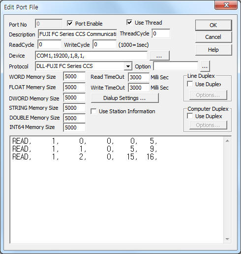
<Figure 1> is read setting example of FUJI FC Series CCS communication driver.
 |
| <Figure 1> Read setting example of FUJI FC Series CCS communication driver |
Device part of <Figure 1> input Com Port(COM1), Baud Rate(19200), Parity Bit(1), Data Bit(8), Stop Bit(1) respectively according to setting of controller.
Note) Baud rate, Parity bit, Data bit, Stop bit are set by using controller's 'setting switch' of front panel.
Default Baud rate, Parity bit, Data bit, Stop bit are 19200 BPS, 1 Parity, 8 Data Bit, 1 Stop Bit.
FUJI FC Series CCS communication driver read schedule
Read schedule setting parameters are as follows:
1) STATION – CCS station number = 1 ~ 31.
2) Read file number – File number = 0 ~ 127. ( Refer to <Table 1> )
3) Read start address – Read start address in each file = 0 ~ 255(varies address according to file area).
4) Save Start Address for Communication Server – saveing start address of Communication Server.
5) Read Size – Read size of Word unit = 1 ~ 16.
Read schedule example)
READ, 1, 0, 0, 0, 5,
READ, 1, 1, 0, 5, 9,
READ, 1, 2, 0, 15, 16,
<Table 1> is file number and contents of FUJI FC Series CCS communication driver.
| File number | File name | Acronym | Write |
| 00 | SCC file | R5SCCFL | Enable |
| 01 | SUB block file | RM1MDFL | - |
| 02 | SUB block parameter file | RM1PRFL | Enable |
| 03 | MAIN block file | RM2MDFL | - |
| 04 | MAIN block parameter file | RM2PRFL | Enable |
| 05 | Wafer output terminal board file | R5TMWFL | - |
| 06 ~ 07 | - | ||
| 08 | Constant terminal board file | R5TMCFL | Enable |
| 09 | Analog terminal board file | R5TMAFL | - |
| 10 | Digital terminal board file | R5TMDFL | |
| 11 | Polygonal line file | R5LNFL | Enable |
| 12 | System table | R5SYSTB | |
| 13 | Dimension table | R5DIMTB | |
| 14 | Wafer execution/connection table | R5WFRTB | |
| 15 | RAS file | R5RASFL | |
| 16 ~ 17 | - | ||
| 18 | Output connection file | R5POCTB | Enable |
| 19 | SCC output connection file | R5SOCTB | |
| 20 | SCC input file | R5SINFL | |
| 21 | SCC output file | R5SOUFL | Disable |
| 22 | Tuning file | R5TUNFL | Enable |
| 23 | Gain schedule file | R5GSTB | |
| 28 | PILC file | R5PILC | |
| <Table 1> File number and contents of FUJI FC Series CCS communication driver | |||
Please refer to Instruction Manual of FUJI FC Series CCS Controller for more data contents and address in each file.
If you click the icon ![]() in protocol option part, you
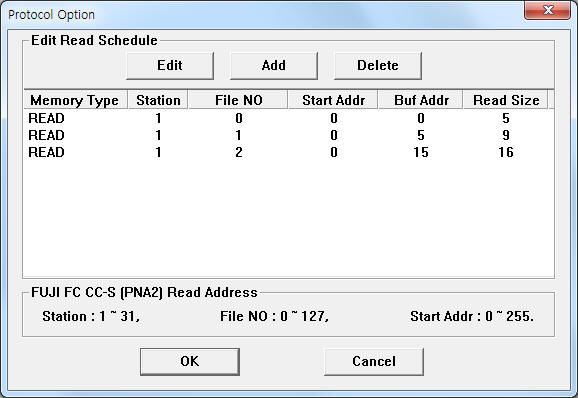
can see the dialogue box such as <Figure 2>. you can also set read schedule by
using this part.
in protocol option part, you
can see the dialogue box such as <Figure 2>. you can also set read schedule by
using this part.
 |
| <Figure 2> Example of FUJI FC Series CCS communication driverí»s Option dialogue box |
You can set read schedule by using ![]() ,
, ![]() ,
, ![]() button and listbox of <Figure
2>.
button and listbox of <Figure
2>.
 |
| <Figure 3> Example of FUJI FC Series CCS communication driverí»s read schedule Add/Edit dialogue box |
When you click Add button or Edit button in dialogue box of <Figure 2>, dialogue box of <Figure 3> is shown.
You can set the file value by using write settings.
Digital Write
Digital write setting parameters are as follows:
1) PORT Port no. (0 ~ 255)
2) STATION CCS station number = 1 ~ 31.
3) ADDRESS Write address in each file = 0 ~ 255(varies address according to file area).
Higher 3 digit : 0 ~ 255 word address,
Lower 1 digit : 0 ~ F bit address.
4) Extra1 Write file number = 0 ~ 127 only writable area. ( Refer to <Table 1>)
5) Extra2 Contents of output.
1 : Output of control, in this case Address, Extra1 = don't care,
0, space, etc : Normal output setting.
Write example 1)
PORT:0, station:1, ADDRESS:0113, Extra1: 4, Extra2 :
The setting parameter shown above is a bit write(On/Off) example of 3(4th) bit, 11(12th) word in 4 file number.
Analog Write
Analog write setting parameters are as follows:
1) PORT Port no. (0 ~ 255)
2) STATION CCS station number = 1 ~ 31.
3) ADDRESS Write address in each file = 0 ~ 255(varies address according to file area).
4) Extra1 Write file number = 0 ~ 127 only writable area. ( Refer to <Table 1>)
5) Extra2 Contents of output.
1 : Output of control, in this case Address, Extra1 = don't care,
0, space, etc : Normal output setting.
Write example 1)
PORT:0, station:1, ADDRESS:0009, Extra1: 4, Extra2 :
The setting parameter shown above is analog write example of 9(10th : P value) word in 4 file number(Main block parameter file).
Write example 2)
PORT:0, station:1, ADDRESS:0010, Extra1: 4, Extra2 :
The setting parameter shown above is analog write example of 10(11th : I value) word in 4 file number(Main block parameter file).
Connection of communication cable, main power and setting baud rate are as follows.
Connection of communication cable
Please connect RS-422/485 communication cable to 4(Tx+), 5(Tx-), 8(Rx+), 9(Tx-) connector of FUJI FC Series CCS Controller such as <Figure 4>. ( usable both 9pin connector )
Computer side FUJI FC Series CCS Controller side
Tx+ --------------------------------- Rx+
Tx- --------------------------------- Rx-
Rx+ --------------------------------- Tx+
Rx- --------------------------------- Tx-
 |
| <Figure 4> Connection example of communication cable and main power to FUJI FC Series CCS |
Connection of main power
Please connect 110V AC to 16(AC), 35(AC) such as <Figure 4>.
<Figure 5> is appearence of FUJI FC Series CCS Controller.
 |
| <Figure 5> Appearence of FUJI FC Series CCS Controller |
Setting of baud rate, data, parity, stop bit
You can set baud rate, data, parity, stop bit by using front panel's 'setting button' of FUJI FC Series CCS Controller. ( Refer to Instruction Manual of FUJI FC Series CCS )