Fuji MICRREX-F communication driver is the driver to communicate with PLC of Fuji Electric Co., Ltd. in Japan.
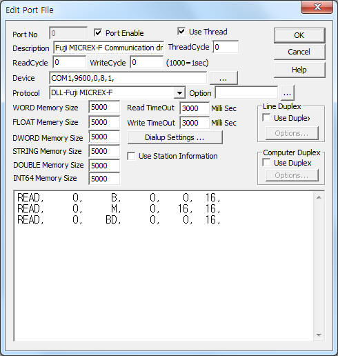
<Figure 1> is read setting example of Fuji MICRREX-F communication driver.
 |
| <Figure 1> Read setting example of Fuji MICRREX-F communication driver |
Device part of <Figure 1> input Com Port(COM1), Baud Rate(9600), Parity Bit(0), Data Bit(8), Stop Bit(1) respectively according to setting of PLC's DIP switch or ladder program.
Fuji MICRREX-F communication driver read schedule
Read schedule setting parameters are as follows:
1) STATION – PLC's station number. RS-232C connection = 0, RS-485 connection = 0 ~ 99.
2) Read command – Read memory type or command = B, M, K, F, A, D, W9, TS, TR, CS, CR, BD, WL, WL2, WB, Wm, WK, WA, WD, W21. ( Refer to <Table 1> )
3) Read start address – Read start address in memory type = 0 ~ .
4) Save Start Address for Communication Server – saveing start address of Communication Server.
5) Read Size – Read size of Word, Dword unit.
Read schedule example)
READ, 0, B, 0, 0, 16,
READ, 0, M, 0, 16, 16,
READ, 0, BD, 0, 0, 16,
Note) Fuji MICREX-F communication driver was made by 'start code = :', 'end code = CR=LF', so you have to set this start and edn code at Ladder program of Fuji PLC.
<Table 1> is read memory type or command and data type of Fuji MICREX-F communication driver.
| Memory type or command | Data type | Remarks |
B |
WORD |
Digital input/output area |
M |
WORD |
Internal memory area |
K |
WORD |
|
F |
WORD |
|
A |
WORD |
|
D |
WORD |
|
W9 |
DWORD |
|
TS |
DWORD |
|
TR |
DWORD |
|
CS |
DWORD |
|
CR |
DWORD |
|
BD |
DWORD |
|
WL |
WORD |
Bit type of WL memory area |
WL2 |
WORD |
Word type of WL memory area |
WB |
BCD_WORD |
Get 16 bit BCD value at B memory area |
WM |
BCD_WORD |
Get 16 bit BCD value at M memory area |
WK |
BCD_WORD |
Get 16 bit BCD value at K memory area |
WF |
BCD_WORD |
Get 16 bit BCD value at F memory area |
WA |
BCD_WORD |
Get 16 bit BCD value at A memory area |
WD |
BCD_WORD |
Get 16 bit BCD value at D memory area |
W21 |
BCD_WORD |
16bit(word ) BCD area |
| <Table 1> Read memory type or command and data type of Fuji MICREX-F communication driver | ||
You can set PLC's memory value by using write settings.
Digital Write
Digital write setting parameters are as follows:
1) PORT Port no. (0 ~ 255)
2) STATION PLC's station number. RS-232C connection = 0, RS-485 connection = 0 ~ 99.
3) ADDRESS Write addres in memory type.
4) Extra1 Write memory type = B,M,K,F,A,D,WL, etc. (only Word data type of <Table 1>)
5) Extra2 Don't care.
Write example 1)
PORT:0, station:0, ADDRESS:0000, Extra1: M, Extra2 :
The setting parameter shown above is a bit write(On/Off) example of M memory type, 0000 address(M0000).
Analog Write
Analog write setting parameters are as follows:
1) PORT Port no. (0 ~ 255)
2) STATION PLC's station number. RS-232C connection = 0, RS-485 connection = 0 ~ 99.
3) ADDRESS Write addres in memory type.
4) Extra1 Write memory type of command at <Table 2> = B, M, K, F, A, D, W9, TS, TR, CS, CR, BD, WL, WL2, WB, Wm, WK, WA, WD, W21.
5) Extra2 Don't care.
Write example 1)
PORT:0, station:0, ADDRESS:0001, Extra1: BD, Extra2 :
The setting parameter shown above is an analog write(dword unit) example of BD memory type, 0001 address(BD0001).