FREQROL 500 Series Inverter communication driver is the driver to communicate with inverter controller of Mitsubishi Electric Corporation in Japan.
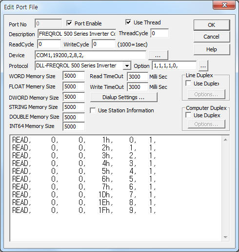
<Figure 1> is read setting example of FREQROL 500 Series Inverter communication driver.
 |
| <Figure 1> Read setting example of FREQROL 500 Series Inverter communication driver |
Device part of <Figure 1> input Com Port(COM1), Baud Rate(19200), Parity Bit(2), Data Bit(8), Stop Bit(2) respectively according to setting of controller.
Baud rate(4800, 600, 1200, 2400,4800, 9600, 19200), parity bit(0, 1, 2), stop bit(1, 2) can set by using 'setting button' of FREQROL 500 Series.
Also you can input 'enable of Link Parameter Expansion's auto setting' (1 : enable, 0 : disable, default = 1), 'type of communication end code'(0 : none, 1 : CR, 2 : CR+LF, default = 1), 'use of Waiting Time in Protocol'(1 : use, 0 : don't use : 0, default = 1), 'Waiting Time when using Waiting Time'(0 ~ 15, unit = 10ms, default = 1), 'send of ACK packet after reading'(1 : send, 0 : don't send : 0, default = 0) by using option part.
Note) When Instruction number of 30(Extended function display selection) = 0(break - MRS type) , the usable Instruction number are 0 ~ 9, 30, 79 ...
Note) Please refer to 4 chapter for setting of controller's station number, baud rate, etc.
FREQROL 500 Series Inverter communication driver read schedule
Read schedule setting parameters are as follows:
1) STATION – Controller's station number = 0 ~ 31.
2) Link Parameter Expansion – Expansion number = 0 ~ 9. ( Refer to <Table 1> or reference manual of FREQROL 500 Series Inverter )
3) Instruction number – Read Instruction number = 0 ~ 127. ( Refer to <Table 1> or reference manual of FREQROL 500 Series Inverter )
4) Save Start Address for Communication Server – saveing start address of Communication Server.
5) Read Size – read word size = fixed to 1.
Read schedule example)
READ, 0, 0, 1h, 0, 1,
READ, 0, 0, 2h, 1, 1,
READ, 0, 0, 3h, 2, 1,
READ, 0, 0, 4h, 3, 1,
READ, 0, 0, 5h, 4, 1,
READ, 0, 0, 6h, 5, 1,
READ, 0, 0, 7h, 6, 1,
READ, 0, 0, 1Dh, 7, 1,
READ, 0, 0, 1Eh, 8, 1,
READ, 0, 0, 1Fh, 9, 1,
Please refer to reference manual of FREQROL 500 Series Inverter for readed data value and contents.
If you click the icon ![]() in protocol option part, you
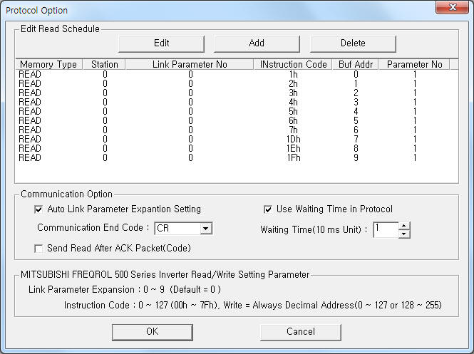
can see the dialogue box such as <Figure 2>. you can also set read schedule by
using this part.
in protocol option part, you
can see the dialogue box such as <Figure 2>. you can also set read schedule by
using this part.
 |
| <Figure 2> Example of FREQROL 500 Series Inverter communication driver¡¯s Option dialogue box |
You can set read schedule by using ![]() ,
, ![]() ,
, ![]() button and listbox of <Figure
2>.
button and listbox of <Figure
2>.
Also you can set enable of Link Parameter Expansion's auto setting, type of communication end code, use of Waiting Time in Protocol, Waiting Time, send of ACK packet after reading at the part of ¡®Communication Option¡¯ shown in <Figure 2>.
 |
| <Figure 3> Example of FREQROL 500 Series Inverter communication driver¡¯s read schedule Add/Edit dialogue box |
When you click Add button or Edit button in dialogue box of <Figure 2>, dialogue box of <Figure 3> is shown.
You can write setting value of inverter by using write settings.
Digital Write
Digital write and Analog write have the same setting parameters except output value(0 or 1).
Analog Write
Analog write setting parameters are as follows:
1) PORT Port no. (0 ~ 255)
2) STATION Controller station number = 1 ~ 31.
3) ADDRESS Write Instruction number = 0 ~ 127( or 128 ~ 255, decimal unit). ( Refer to <Table 1> or reference manual of FREQROL 500 Series Inverter )
4) Extra1 Expansion number = 0 ~ 9. ( Refer to <Table 1> or reference manual of FREQROL 500 Series Inverter )
5) Extra2 Number of writing bytes.(default = 2)
1 : 1 byte data,
3 : 3 byte data,
2, space, ... : 2 byte data. (default)
Note) In order to write some Instruction number, you should be set 'EXT' mode of Inverter's communication mode.
Also when the 77 Instruction number's value equal 1 or 0 and PU operation mode equal don't stop, you can't set most of the parameter. (you can set 75, 77, 79, .. Instruction parameters)
But you can set parameter when the 77 Instruction number's value equal 2 regardless of PU mode.
Write example 1)
PORT:0, station:0, ADDRESS:0001, Extra1: 0, Extra2 :
The setting parameter shown above is maximum frequency setting example of 0 station FREQROL 500 Series Inverter.
Write example 2)
PORT:0, station:0, ADDRESS:0002, Extra1: 0, Extra2 :
The setting parameter shown above is minimum frequency setting example of 0 station FREQROL 500 Series Inverter.
Connection of communication cable and main power are as follows.
Connection of communication cable
Please connect RS-485 communication cable to RS-485 connector of FREQROL 500 Series Inverter such as <Figure 4>.
PU connector of FREQROL 500 Series RS-485 connector of computer
3 connector(RDA) -------------------------------------------- SDA(T+)
4 connector (SDB) -------------------------------------------- RDB(R-)
5 connector (SDA) -------------------------------------------- RDA(R+)
6 connector (RDB) -------------------------------------------- SDB(T-)
<Figure 4> RS-485 communication cable daigram between FREQROL 500 Series Invert(PU connector) amd computer
<Figure 5> is connection example of communication cable and main power to FREQROL 500 Series Inverter.
 |
| <Figure 5> Connection example of communication cable and main power to FREQROL 500 Series Inverter |
Connection of main power
Please connect 220V AC or 3 phase power to R.S.T such as <Figure 5>.
<Figure 6> is appearence of FREQROL 500 Series Inverter.
 |
| <Figure 6> Appearence of FREQROL 500 Series Inverter |
You can set controller station address, baud rate, ... by using front panel' setting button of FREQROL 500 Series inverter.
Also you can set by using write settings.
Note) After setting the controller station, baud rate, etc, you have to reset(power reset or reset command) the controller.
Setting of controllser station number
Controller station number can be set as follows:
1) Press 'MODE' button at normal operation status. Then will display 'Instruction(P0 ~ P127, n0 ¡¦ ) at the screen.
2) Please set 'n1 Instruction' by using dial switch.
3) Press 'SET' button, then will display current setting station number.
4) Set the station what you want by using dial switch.
5) After setting the station, press 'SET' button.
6) Press 'MODE' button 2 times, then will goes back to the normal operation status.
Setting of baud rate
Baud rate number can be set as follows:
1) Press 'MODE' button at normal operation status. Then will display 'Instruction(P0 ~ P127, n0 ¡¦ ) at the screen.
2) Please set 'n2 Instruction' by using dial switch.
3) Press 'SET' button, then will display current setting baud rate(48, 96, 192, etc).
4) Set the baud rate what you want by using dial switch.
5) After setting the baud rate, press 'SET' button.
6) Press 'MODE' button 2 times, then will goes back to the normal operation status.
Setting of extended function display selection
Extended function display selection number can be set as follows:
1) Press 'MODE' button at normal operation status. Then will display 'Instruction(P0 ~ P127, n0 ¡¦ ) at the screen.
2) Please set 'P 30 Instruction' by using dial switch.
3) Press 'SET' button, then will display current setting extended function display selection(0 or 1).
4) Set the extended function display selection what you want by using dial switch.
5) After setting the extended function display selection, press 'SET' button.
6) Press 'MODE' button 2 times, then will goes back to the normal operation status.
Setting of communication End Code
Communication End Code can be set as follows:
1) Press 'MODE' button at normal operation status. Then will display 'Instruction(P0 ~ P127, n0 ¡¦ ) at the screen.
2) Please set 'n 11 Instruction' by using dial switch.
3) Press 'SET' button, then will display current setting communication End Code(0, 1, 2).
4) Set the communication End Code what you want by using dial switch( 0 = none, 1 = CR, 2 = CR+LF ).
5) After setting the communication End Code, press 'SET' button.
6) Press 'MODE' button 2 times, then will goes back to the normal operation status.
Setting of waiting time
Waiting time can be set as follows:
1) Press 'MODE' button at normal operation status. Then will display 'Instruction(P0 ~ P127, n0 ¡¦ ) at the screen.
2) Please set 'n 7 Instruction' by using dial switch.
3) Press 'SET' button, then will display current setting waiting time(0 ~ 150 or 65535).
4) Set the waiting time what you want by using dial switch(0 ~ 150 or etc).
5) After setting the waiting time, press 'SET' button.
6) Press 'MODE' button 2 times, then will goes back to the normal operation status.
Note) When Instruction number of 30(Extended function display selection) = 0(break - MRS type) , the usable Instruction number are 0 ~ 9, 30, 79 ... and can't set controller station, baud rate, etc.
If you want to set controller station, baud rate, etc, you have to set 'Extended function display selection' = 1.
<Table 1> is a Instruction number, Link Parameter Expansion number and contents of FREQROL 500 Series Inverter.


<Table 1> Instruction number, Link Parameter Expansion number and contents of FREQROL 500 Series Inverter