FCU 2000 Version 4 Communication Driver is the driver to communicate with building automation controller of Shin-A System Co., Ltd. in Korea.
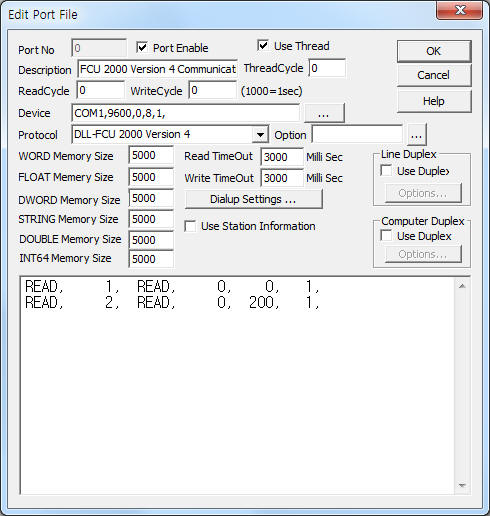
<Figure 1> is read setting example of FCU 2000 Version 4 communication driver.
 |
| <Figure 1> Read setting example of FCU 2000 Version 4 communication driver |
Device part of <Figure 1> input Com Port(COM1), Baud Rate(9600), Parity Bit(0), Data Bit(8), Stop Bit(1) respectively.
FCU 2000 controller's baud rate, data bit, stop bit are fixed to 9600, 0, 8, 1.
Controller station number of FCU 2000 can set 0 ~ 63. ( Refer to chapter 4 )
Also you can set 'save gap of each data area'(64 ~ 1000, default : 64) by using option part.
FCU 2000 Version 4 communication driver read schedule
Read schedule setting parameters are as follows:
1) STATION – Controller station address = 0 ~ 63.
2) Read Command – Fixed to READ.
3) Read Start Address – Don't care.
4) Save Start Address for Communication Server – saveing start address of Communication Server.
5) Read Size – read wird size = fixed to 193.
Read schedule example)
READ, 1, READ, 0, 0, 1,
READ, 2, READ, 0, 200, 1,
Note) FCU 2000 Version 4 communication driver save the readed data to WORD(BI, BO, BD) and FLOAT(AI, AO, AD) memory. ( Refer to <Table 1> )
<Table 1> is data saving address and memory type of FCU 2000 Version 4 communication driver.
| Data Saving Address | WORD memory | FLOAT memory | |
| High byte | Low byte |
||
| Start Add + 0 | DDC
Type 1 = FCU, 2 = LCU |
XimSts(status value of extenede module) |
--- |
| Start Add + 1 ~ 64 | 1 ~ 64 AI point status value |
1 ~ 64 High 4bits(nibble) = BI high nibble status, Low 4bits(nibble) = BI low nibble status |
1 ~ 64 current value of AI |
| Start Add + save gap of each area + 1 ~ 64 (default : Start Add + 65 ~ 128) |
1 ~ 64 AO point status value |
1 ~ 64¹ø High 4bits(nibble) = BO high nibble status, Low 4bits(nibble) = BO low nibble status |
1 ~ 64 current value of AO |
| Start Add + (save gap of each area x 2) + 1 ~ 64 (default : Start Add + 129 ~ 192) |
1 ~ 64 AD point status value |
1 ~ 64¹ø High 4bits(nibble) = BD high nibble status, Low 4bits(nibble) = BD low nibble status |
1 ~ 64 current value of AD |
| <Table 1> Data saving address and memory type of FCU 2000 Version 4 communication driver (when save gap of each area = 64) | |||
If you click the icon ![]() in protocol option part, you
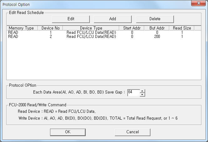
can see the dialogue box such as <Figure 2>. you can also set read schedule by
using this part.
in protocol option part, you
can see the dialogue box such as <Figure 2>. you can also set read schedule by
using this part.
 |
| <Figure 2> Example of FCU 2000 Version 4 communication driver¡¯s Option dialogue box |
You can set read schedule by using ![]() ,
, ![]() ,
, ![]() button and listbox of <Figure
2>.
button and listbox of <Figure
2>.
Save gap of each data area can input by using the part of ¡®Each Data Area(AI, AO, AD, BI, BO, BD) Save Gap' shown in <Figure 2>.
 |
| <Figure 3> Example of FCU 2000 Version 4 communication driver¡¯s read schedule Add/Edit dialogue box |
When you click Add button or Edit button in dialogue box of <Figure 2>, dialogue box of <Figure 3> is shown.
You can control or change of FCU 2000 controller's value by using write settings.
Digital Write
Digital write setting parameters are as follows:
1) PORT Port no. (0 ~ 255)
2) STATION Controller station address = 0 ~ 63.
3) ADDRESS Write decimal address = 1 ~ 64 according to write data type.
4) Extra1 Write data type.
AI or 1 : setting of AI current,
AO or 2 : setting of AO current,
AD or 3 : setting of AD current,
BI, DI or 4 : setting of BI current,
BO, DO, space, 5, ¡¦ : setting of BO current,
BD, DD or 6 : setting of BD current.
5) Extra2 Priority number of command.
1 : Release Priority(CMD_REL),
2, 0, ¡¦ : Operator Command Priority(CMD_OPER, normal command),
3 : Control Logic Command Priority(CMD_CTL),
4 : Schedule Command Priority(CMD_SCH),
5 : Software Override Priority(CMD_SWO),
6 : Software Override Release Priority(CMD_SWR),
7 : Manual Override Priority(CMD_OVR),
8 : Initial Status Priority(CMD_INIT, real priority number = 0 )
Write example 1)
PORT:0, station:1, ADDRESS:0001, Extra1: , Extra2 : 2
The setting parameter shown above is a control(On/Off) example of address = 1, data type = BO at FCU 2000 controller connected with 0 port, 1 station address.
Write example 2)
PORT:0, station:2, ADDRESS:0008, Extra1: 5, Extra2 : 2
The setting parameter shown above is a control(On/Off) example of address = 8, data type = BO at FCU 2000 controller connected with 0 port, 2 station address.
Analog Write
Analog write setting parameters are as follows:
1) PORT Port no. (0 ~ 255)
2) STATION Controller station address = 0 ~ 63.
3) ADDRESS Write decimal address = 1 ~ 64 according to write data type.
4) Extra1 Write data type.
AI or 1 : setting of AI current,
AO or 2 : setting of AO current,
AD or 3 : setting of AD current,
BI, DI or 4 : setting of BI current,
BO, DO, space, 5, ¡¦ : setting of BO current,
BD, DD or 6 : setting of BD current.
5) Extra2 Priority number of command.
1 : Release Priority(CMD_REL),
2, 0, ¡¦ : Operator Command Priority(CMD_OPER, normal command),
3 : Control Logic Command Priority(CMD_CTL),
4 : Schedule Command Priority(CMD_SCH),
5 : Software Override Priority(CMD_SWO),
6 : Software Override Release Priority(CMD_SWR),
7 : Manual Override Priority(CMD_OVR),
8 : Initial Status Priority(CMD_INIT, real priority number = 0 )
Write example 1)
PORT:0, station:1, ADDRESS:0005, Extra1: , Extra2 : 2
The setting parameter shown above is a setting example of address = 5, data type = AO at FCU 2000 controller connected with 0 port, 1 station address.
Write example 2)
PORT:0, station:2, ADDRESS:0007, Extra1: 2, Extra2 : 2
The setting parameter shown above is a setting example of address = 7, data type = AO at FCU 2000 controller connected with 0 port, 2 station address.
Connection of communication cable and main power are as follows.
Connection of communication cable
Please connect normal RS-232C or RS-485 communication cable to terminal port, Xm-Net communication port such as <Figur 4>.
RJ45 connector of FCU 2000 controller 9 pin connector of computer
5 -------------------------------------------------- 2 of RS232C connector (Rx)
4 -------------------------------------------------- 3 of RS232C connector (Tx)
2 -------------------------------------------------- 5 of RS232C connector (Ground)
<Figure > 4> is specifications and explanation of FCU 2000 controller
 |
| <Figure 4> Specifications and explanation of FCU 2000 controller |
Connection of communication cable with MCU controller
You can connect RS-232C or RS-485 communication cable to serial connector of MCU(Master Control Unit) controller such as <Figur 5>.
<Figure>, <Figure > 6> are specifications and explanation of MCU 5000, LCU 1000 controller.
 |
| <Figure 5> Specifications and explanation of MCU 5000 controller |
 |
| <Figure 6> Specifications and explanation of LCU 1000 controller |
Connection of main power
Please connect 24V AC ( max 0.5 A) main power to H, N connector to FCU 2000 controller such as <Figure 4>.
Note) FCU 2000 Version 4 controller main power use 24V AC.
You can set FCU 2000(or LCU-1000 ...) controller's station number by using SW1 Dip 1 ~ 8(currently use 1 ~ 5) switch.
Setting example) Dip 1 = On : station number = 1
Dip 5 = On : station number = 16