FC-600 Communication Driver is the driver to communicate with DRS flow controller of NKE System Co., Ltd. in Korea.
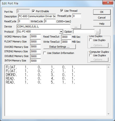
<Figure 1> is read setting example of FC-600 communication driver.
 |
| <Figure 1> Read setting example of FC-600 communication driver |
Device part of <Figure 1> input Com Port(COM1), Baud Rate(9600), Parity Bit(0), Data Bit(8), Stop Bit(1) respectively, according to setting of controller.
FC-600 communication driver read schedule
Read schedule setting parameters are as follows:
1) STATION – Controller station address = 0 ~ 255.
2) Read Command – Don't care.
3) Read Start Address – read start address = 1 ~ 23. ( Refer to <Table 1> )
4) Save Start Address for Communication Server – saveing start address of Communication Server.
5) Read Size – read wird size = fixed to 1.
Read schedule example)
FLOAT, 1, 0, 1, 0, 1,
FLOAT, 1, 0, 2, 1, 1,
DWORD, 1, 0, 3, 0, 1,
READ, 1, 0, 4, 0, 1,
READ, 1, 0, 5, 1, 1,
<Table 1> is read/write address and contents of FC-600 controller.
| Address | Contents | Readed data type |
Remarks |
| 1, | Rate 1 | FLOAT |
|
| 2, | Total 1 | FLOAT |
R/W |
| 3, | Pressure 1 | FLOAT |
|
| 4, | Level Alarm l | WORD |
|
| 5, | Pump Status l | WORD |
ON = 1, OFF = 0, R/W |
| 6, | Rate 2 | FLOAT |
|
| 7, | Total 2 | FLOAT |
R/W |
| 8, | Pressure 2 | FLOAT |
|
| 9, | Level Alarm 2 | WORD |
|
| 10, | Pump Status 2 | WORD |
ON = 1, OFF = 0, R/W |
| 11, | Rate 3 | FLOAT |
|
| 12, | Total 3 | FLOAT |
R/W |
| 13, | Pressure 3 | FLOAT |
|
| 14, | Level Alarm 3 | WORD |
|
| 15, | Pump Status 3 | WORD |
ON = 1, OFF = 0, R/W |
| 16, | Rate 4 | FLOAT |
|
| 17, | Total 4 | FLOAT |
R/W |
| 18, | Pressure 4 | FLOAT |
|
| 19, | Level Alarm 4 | WORD |
|
| 20, | Pump Status 4 | WORD |
ON = 1, OFF = 0, R/W |
| 21, | Analog Output | WORD |
R/W |
| 22, | ch1 Analog | Output WORD |
R/W |
| 23, | ch2 Analog | Output WORD |
R/W |
| <Table 1> Read/write address and contents of FC-600 controller | |||
You can control or change of FC-600 controller's value by using write settings.
Digital Write
Digital write setting parameters are as follows:
1) PORT Port no. (0 ~ 255)
2) STATION Controller station address = 0 ~ 255.
3) ADDRESS Write decimal address = 0005, 0010, 0015, 0020, .... ( Refer to <Table 1> )
4) Extra1 Don't care.
5) Extra2 Don't care.
Write example 1)
PORT:0, station:1, ADDRESS:0005, Extra1: , Extra2 :
The setting parameter shown above is Pump Status control(On/Off) example of FC-600 connected with 0 port, 1 controller station address.
Analog Write
Analog write setting parameters are as follows:
1) PORT Port no. (0 ~ 255)
2) STATION Controller station address = 0 ~ 255.
3) ADDRESS Write decimal address = 0021~0023, .... ( Refer to <Table 1> )
4) Extra1 Don't care.
5) Extra2 Don't care.
Write example 1)
PORT:0, station:1, ADDRESS:0021, Extra1: , Extra2 :
The setting parameter shown above is an 'Analog Output' write example of FC-600 connected with 0 port, 1 controller station address.