ETLC Lighting Controller is the driver to communicate with lighting controller(6SRM) of M.R Engineering Co., Ltd. in Korea.
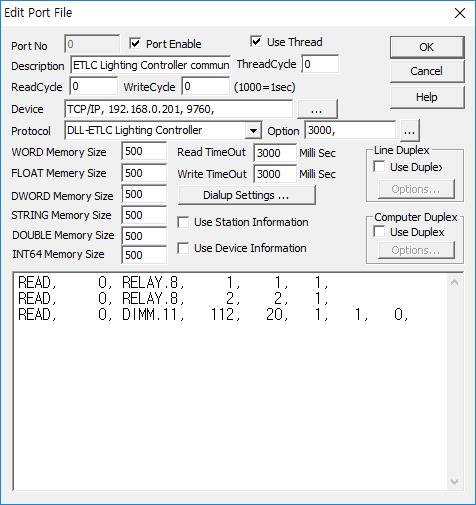
<Figure 1> is read setting example of ETLC Lighting Controller communication driver.
|
|
| <Figure 1> Read setting example of ETLC Lighting Controller communication driver |
Device part of <Figure 1> input device type(TCP/IP), IP address of controller(192.168.0.201), service port(9760) respectively, accordint to the setting of controller.
Read schedule of ETLC Lighting Controller communication driver
Read schedule setting parameters are as follows:
1) SCU address – 0 ~ 63 SCU address.
2) Read command – RELAY, DIMM, LIVE. ( refer to <Table 1>, default pannel type : RELAY = 6SRM, DIMM = DALI )
pannel type setting : RELAY.xx, DIMM.xx,
xx = pannel type, 0 - SMARTROL, 1 - SCU, 2 - 4DSW, 3 - 8DSW, 4 - STS1, 5 - STS2, 6 - SU, 7 - 4SRM, 8 - 6SRM, 9 - ERM 4,6, 10 - 48SRM, 11 -DALI.
3) Device address – 0 ~ 1023 Device address.
4) Save start address for Communication Server – Saving start address of Communication Server.
5) Read size – fixed to 1.
6) Dimmer Group address - 1 ~ 4 dimmer group address for DIMM read command.
Read schedule example)
READ, 0, RELAY.8, 1, 1, 1,
READ, 0, RELAY.8, 2, 2, 1,
READ, 0, DIMM.11, 112, 20, 1, 1,
<Table 1> is readed data and saving address for ETLC Lighting Controller communication driver.
Read commnad |
Contents |
Data saving value for Communication Server |
Remarks |
RELAY |
read of current Relay status |
Start Saving Address + 0 : Relay status value |
0 ~ 5 Bit : ON/OFF status of 1 ~ 6 Sub address(each bit) |
DIMM |
read of current Dimmer value |
Start Saving Address + 0 ~ 15 : current dimmer value for each dimmer group |
1 ~ 4 Group 1 Group : Dimmer 1 ~ 16 2 Group : Dimmer 17 ~ 32 3 Group : Dimmer 33 ~ 48 4 Group : Dimmer 49 ~ 64 |
LIVE |
Network alive check |
Start Saving Address + 0 : ETLC Line status |
|
| <Table 1> Readed data and saving address for ETLC Lighting Controller communication driver | |||
ETLC Lighting Controller communication driver store the same data in WORD, DWORD, FLOAT, DOUBLE memory, but the data format are different.
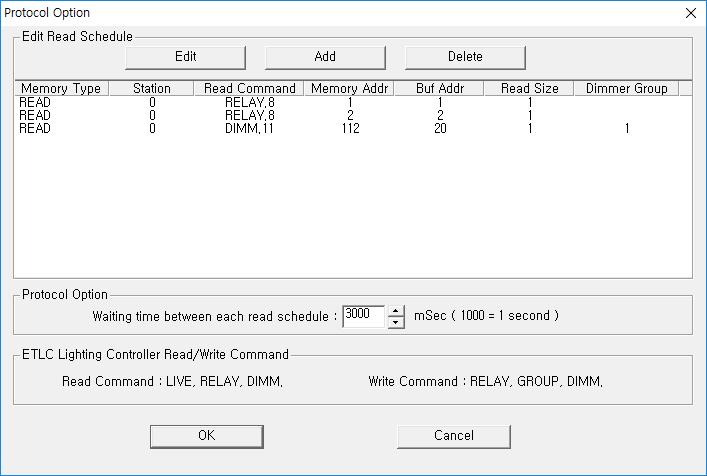
If you click the icon ![]() in protocol option part at
<Figure 1>, you
can see the dialog box such as <Figure 2>. you can also set read schedule by
using this part.
in protocol option part at
<Figure 1>, you
can see the dialog box such as <Figure 2>. you can also set read schedule by
using this part.
 |
|
<Figure 2> Example of ETLC Lighting Controller communication driver’s Option dialog box |
You can set read schedule by using
![]() ,
,
![]() ,
,
![]() button and listbox of <Figure
2>.
button and listbox of <Figure
2>.
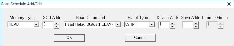 |
| <Figure 3> Example of ETLC Lighting Controller communication driver’s read schedule Add/Edit dialog box |
When you click Add button or Edit button in dialogue box of <Figure 2>, dialogue box of <Figure 3> is shown.
You can control Relay status by using 'write settings'.
Digital Write
Digital write and analog write have the same setting parameters except output value.
Analog Write
Analog write setting parameters are as follows:
1) PORT Port no. (0 ~ 255)
2) STATION 0 ~ 63 SCU address.
3) ADDRESS 0 ~ 1023 Device address.
4) Extra1 Write command : RELAY, DIMM, GROUP. ( GROUP : don't read ok signal, , default pannel type : RELAY, GROUP = 6SRM, DIMM = DALI )
pannel type setting : RELAY.xx, DIMM.xx,
xx = pannel type, 0 - SMARTROL, 1 - SCU, 2 - 4DSW, 3 - 8DSW, 4 - STS1, 5 - STS2, 6 - SU, 7 - 4SRM, 8 - 6SRM, 9 - ERM 4,6, 10 - 48SRM, 11 -DALI.
5) Extra2 RELAY, GROUP write command : 0 ~ 5 Sub address,
DIMM write command : 1 ~ 64 Dimmer sub address.
Write example 1)
PORT : 0 STATION : 0 ADDRESS : 0003 EXTRA1 : ID EXTRA2 : 1
The setting parameter shown above is Relay control ( ON or OFF ) example of 0 SCU address, 3 Device address, 1( 2nd ) Sub address Relay.
Write example 2)
PORT : 0 STATION : 0 ADDRESS : 0001 EXTRA1 : DIMM.11 EXTRA2 : 1
The setting parameter shown above is Dimmer value setting( 0 ~ 254, 0 = off) example for 0 SCU address, 1 Device address, 1( 1st ) Dimmer sub address.
<Figure 4> shows the appearance of ETLC Lighting controller.
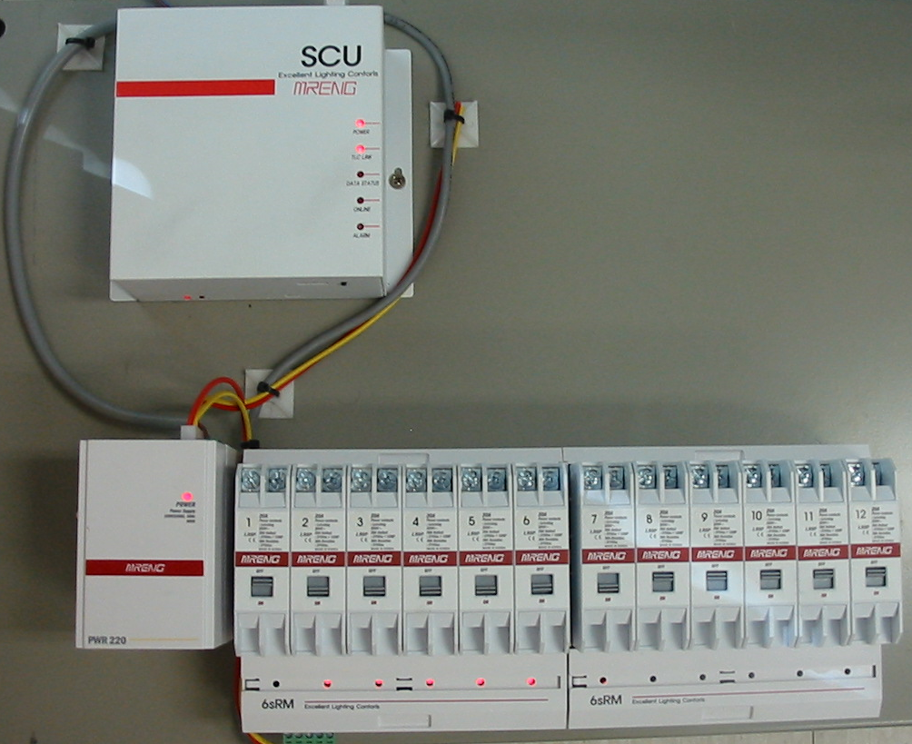 |
| <Figure 4> Appearance of ETLC Lighting controller |