EMS(Electricity Measurement System)-MODBUS communication driver is the driver to communicate with power meter EMS 43/400/410/420/4000/4001/4010 ¡¦ series of ALGODUE electronica in Italy.
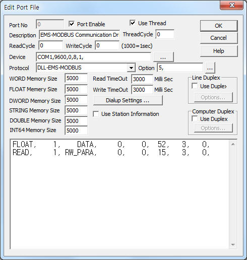
<Figure 1> is read setting example of EMS-MODBUS communication driver.
 |
| <Figure 1> Read setting example of EMS-MODBUS communication driver |
Device part of <Figure 1> input Com Port(COM1), Baud Rate(9600), Parity Bit(0), Data Bit(8), Stop Bit(1) respectively, according to setting of controller.
EMS-43 controller can set baud rate(300, 600, 1200, 2400,4800, 9600), parity bits(0, 1, 2), stop bits(1, 2) by using setting of communication parameter or front panel's setting button.
Also you can input 'write after wait time' (0 ~ , default : 3 seconds) by using option part.
EMS-MODBUS communication driver¡¯s read schedule
Read schedule setting parameters are as follows:
1) Station – Controller station number = 1 ~ 255.
2) Read Command – Command = DATA, MINMAX, HAR, COUNTER, PARA, RW_PARA, BYTE, WORD, DWORD, FLOAT.
DATA – Read of Measured Value, ( Refer to <Table 2> )
MINMAX – Read of MIN/MAX Value, (EMS-400 or upper model)
HAR – Read of Harmonics Value, (EMS-4001 or upper model)
COUNTER – Read of Time Energy Band Counter, (Option)
PARA – Read of Only Read EMS Parameter,
RW_PARA – Read of Read & Write EMS Parameter,
BYTE – Byte unit data read of Modbus protocol,
WORD – Word unit data read of Modbus protocol,
DWORD – Double word unit data read of Modbus protocol,
FLOAT – Float unit data read of Modbus protocol.
3) Read Start Address – Read start address according to Read Command.
4) Save start address for Communication Server – Saving start address of Communication Server.
5) Read Size – read size of byte/word/float... unit. ( Refer to <Table 1> )
6) Modbus Function – Modbus function number. ( 3, 4, ... )
Read schedule example)
FLOAT, 1, DATA, 0, 0,
52, 3,
READ, 1, RW_PARA, 0, 0, 15,
3,
<Table 1> is max read size and data type according to Read Command.
| Read Command | Max read size (when EMS-4010 model) |
Data Type |
| DATA | 64 | FLOAT |
| MINMAX | 125 | |
| HAR | 150 | |
| COUNTER | 48 | 4 WORD |
| PARA | 22 | WORD |
| RW_PARA | 18 | |
| BYTE, WORD, DWORD, FLOAT |
Vary according to the setting address |
BYTE, WORD, DWORD FLOAT |
| <Table 1> Max read size and data type according to Read Command | ||
<Table 2> is data saving address and contents of DATA read command. (when EMS-4010 model)
Data Saving Address |
Contents |
Units |
Range |
modbus address (Hex Decimal) |
| Start Add + 0 | 3-PHASE system voltage | mV | Unsigned | 1000h~ 1001h |
| Start Add + 1 ~ 3 | L1 ~ L3 PHASE voltage | 1002h~ 1007h | ||
| Start Add + 4 ~ 6 | L12, L21, L31 LINE voltage | 1008h~ 100Dh | ||
| Start Add + 7 | 3-PHASE system current | mA | Signed | 100Eh~ 100Fh |
| Start Add + 8 ~ 10 | L1 ~ L3 LINE current | 1010h~ 1015h | ||
| Start Add + 11 | 3-PHASE system Power Factor | - | 1016h~ 1017h | |
| Start Add + 12 ~ 14 | L1 ~ L3 Power Factor | 1018h~ 101Dh | ||
| Start Add + 15 | 3-PHASE system Cos (4001 or upper model) | 101Eh~ 101Fh | ||
| Start Add + 16 ~ 18 | L1 ~ L3 PHASE Cos (4001 or upper model) | 1020h~ 1025h | ||
| Start Add + 19 | 3-PHASE system Apparent power | mVA | 1026h~ 1027h | |
| Start Add + 20 ~ 22 | L1 ~ L3 Apparent power | 1028h~ 102Dh | ||
| Start Add + 23 | 3-PHASE system Active power | mW | 102Eh~ 102Fh | |
| Start Add + 24 ~ 26 | L1 ~ L3 Active power | 1030h~ 1035h | ||
| Start Add + 27 | 3-PHASE system Reactive power | mVAR | 1036h~ 1037h | |
| Start Add + 28 ~ 30 | L1 ~ L3 Reactive power | 1038h~ 103Dh | ||
| Start Add + 31 | 3-PHASE system Active Energy+ | mWh | Unsigned | 103Eh~ 103Fh |
| Start Add + 32 | 3-PHASE system Reactive Energy+ | mVARh | 1040h~ 1041h | |
| Start Add + 33 | 3-PHASE system Active Energy- (400 or upper model) | mWh | 1042h~ 1043h | |
| Start Add + 34 | 3-PHASE system Reactive Energy- (400 ..) | mVARh | 1044h~ 1045h | |
| Start Add + 35 | Frequency | mHZ | 1046h~ 1047h | |
| Start Add + 36 ~ 38 | L1 ~ L3 THD voltage (400 or upper model) | m% | 1048h~ 104Dh | |
| Start Add + 39 ~ 41 | L1 ~ L3 THD current (4001 or upper model) | m% | 104Eh~ 1053h | |
| Start Add + 42 | 3-PHASE average power | mW | 1054h~ 1055h | |
| Start Add + 43 | 3-PHASE average current (400 or upper model) | mA | 1056h~ 1057h | |
| <Table 2> Data saving address and contents of DATA read command | ||||
Note) Please refer to EMS series manual or help for Read/Write command of MINMAX, HAR, COUNTER, PARA, RW_PARA, BYTE, WORD, DWORD, FLOAT.
If you click the icon ![]() in protocol option part, you
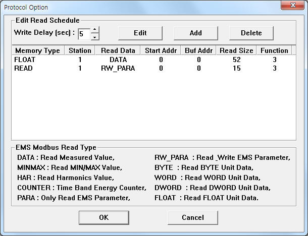
can see the dialogue box such as <Figure 2>. you can also set read schedule by
using this part.
in protocol option part, you
can see the dialogue box such as <Figure 2>. you can also set read schedule by
using this part.
 |
| <Figure 2> Example of EMS-MODBUS communication driver¡¯s Option dialogue box |
You can set read schedule by using ![]() ,
, ![]() ,
, ![]() button and listbox
of <Figure 2>.
button and listbox
of <Figure 2>.
 |
| <Figure 3> Example of EMS-MODBUS communication driver¡¯s read schedule Add/Edit dialogue box |
When you click Add button or Edit button in dialogue box of <Figure 2>, dialogue box of <Figure 3> is shown.
You can write setting value by using write settings.
Digital Write
Digital write and analog write have the same setting parameters except output value.
Analog Write
Analog write setting parameters are as follows:
1) PORT Port no. (0 ~ 255)
2) STATION Controller station number = 1 ~ 255.
3) ADDRESS Hex-decima write address.
DIRECT command : write address of modbus(hex-decimal unit),
other command : relative write address(hex-decimal unit).
4) Extra1 Write command.
CT : CT ratio setting of EMS Power Meter,
VT : VT value setting of EMS Power Meter,
DO1 : Write of Out Digit 1 Mode, Variable, Pulse ¡¦,
DO2 : Write of Out Digit 2 Mode, Variable, Pulse ¡¦,
DO3 : Write of Out Digit 3 Mode, Variable, Pulse ¡¦,
DO4 : Write of Out Digit 4 Mode, Variable, Pulse ¡¦,
AO1 : Write of Out Analog 1 Mode, Variable, Limit ¡¦,
AO2 : Write of Out Analog 2 Mode, Variable, Limit ¡¦,
AO3 : Write of Out Analog 3 Mode, Variable, Limit ¡¦,
AO4 : Write of Out Analog 4 Mode, Variable, Limit ¡¦,
RESET : Reset Consumption Energy Counter, (Output value = 1 : reset count, 2 : reset time bands, 3 : reset all)
RAM_CLR : Reset of saved RAM, (Output value = 9 : deleting all)
DIRECT : Write of Modbus Address by WORD/BYTE unit.
5) Extra2 Byte number of writing data.
1 : 1 byte data,
2, ... : 2 byte data(default).
Write example 1)
Port : 0, Station : 1, Address : 0000, Extra1 : CT, EXTRA2 : , Output value = 512 ( 200h), EMS model = EMS-4010,
The setting parameter shown above is a setting example of high byte fo CT ration, setting value = 2.
Write example 2)
Port : 0, Station : 2, Address : 0000, Extra1 : CT, EXTRA2 : , Output value = 5, EMS model = EMS-420,
The setting parameter shown above is a CT ratio setting example of 2 EMS-420 station number, setting value = 3.
Write example 3)
Port : 0, Station : 1, Address : 0000, Extra1 : RESET, EXTRA2 : , Output value = 3
The setting parameter shown above is a reset example of all Consumption Energy Counter.
Write example 4)
Port : 0, Station : 1, Address : 0A960, Extra1 : DIRECT, EXTRA2 : , Output value = 3
The setting parameter shown above is a reset example of all Consumption Energy Counter.
Connection of communication cable and main power line are as follows.
Connection of communication cable
Please connect EMS controller¡¯s +, - RS-485 connector and +. - RS-485 connector of computer respectively.
RS-485 connector of computer RS-485 connector of EMS series
+ (Tx+, Rx+) --------------------------- +
- (Tx-, Rx-) ----------------------------- -
RS-485 communication cable connection of EMS-43 model
Please connect 7( - ), 8( + ) connector and +, - RS-485 connector of computer. ( Refer to <Figure 4> )
 |
| <Figure 4> Front side appearence of EMS-43 model |
Communication cable connection of EMS-4010 model
Please connect RS-232C or RS-485 serial communication cable such as <Figure 5>, <Table 3>.
 |
| <Figure 5> Communication cable connection method of EMS-4010 model |
|
3 2 1 |
4 3 2 1 |
RS-232C |
Gnd Tx Rx |
On Off On Off |
RS-485 |
+ - Com |
Off On Off On |
| <Table 3> Wiring of RS-232C, RS-485 communication cable for EMS-4010 model | ||
Connection of main power
Please connect 60 ~ 265V, 45/65 HZ or 90 ~ 350 V DC power to L, N connector of EMS series controller.
Setting of meter address and baud rate
You can set EMS controller's station address(1 ~ 247) and baud rate by using front panel's setting button or communication.