EESYS CCU Controller Communication Driver is the driver to communicate with CCU equipment of EESYS Co., Ltd. in Korea.
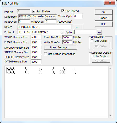
<Figure 1> is read setting example of EESYS CCU Controller communication driver.
|
|
| <Figure 1> Read setting example of EESYS CCU Controller communication driver |
Device part of <Figure 1> input Com Port(COM8), Baud Rate(9600), Parity Bit(0), Data Bit(8), Stop Bit(1) respectively.
EESYS CCU Controller communication driver’s read schedule
Read schedule setting parameters are as follows:
1) STATION – Don't care.
2) Read command – Command = P, D, CHARGE, FARE .(Refer to <Table 1>)
3) Read Start Address – Don't care.
4) Save Start Address for Communication Server – Saving start address of Communication Server.
5) Read Size – Size = Fix to 1.
Read schedule example)
READ, 0, P, 0, 0, 1,
READ, 0, D, 0, 300, 1,
<Table 1> is a description of read command and stored values of EESYS CCU Controller communication driver.
| Read Command | Contents | Stored Values or Output value | Remarks |
| P | Read of charge operation status | Start Add + 0 ~ 2 : System output voltage/current/power Start Add + 3 ~ 5 : System input voltage/current/power Start Add + 6 ~ 7 : Charging remain time minute/second Start Add + 8 ~ 9 : Total charging time minute/second Start Add + 10 ~ 11 : CCU Fault/CCU Run, stop Start Add + 12 ~ 13 : Reserved 1/2 Start Add + 14 ~ 16 : BMS operation status/charging plug connection status/BMS Fault Start Add + 17 ~ 18 : Reserved 1/2 Start Add + 19 ~ 21 : Battery Fault 1/2, Reserved 2 *************** PS 1 ~ 10 status value ******************************* Start Add + 22 ~ 23 : P/S 1 R input voltage/current Start Add + 24 ~ 25 : P/S 1 S input voltage/current Start Add + 26 ~ 27 : P/S 1 Status/end stauts = 1 Start Add + 28 ~ 29 : P/S 1 T input voltage/current Start Add + 30 ~ 31 : P/S 1 DC voltage/output voltage Start Add + 32 : P/S 1 end status = 2 Start Add + 33 ~ 34 : P/S 1 DC current/output current Start Add + 35 ~ 38 : P/S 1 Fault 1 ~ 4 Start Add + 39 : P/S 1 end status = 3 Start Add + 40 ~ 47 : reserved 1 ~ 8 Start Add + 48 ~ 73 : P/S 2 R input voltage ~ reserved 8(Module 2 status value) Start Add + 74 ~ 99 : P/S 3 R input voltage ~ reserved 8(Module 3 status value) Start Add + 100 ~ 125 : P/S 4 R input voltage ~ reserved 8(Module 4 status value) Start Add + 126 ~ 151 : P/S 5 R input voltage ~ reserved 8(Module 5 status value) Start Add + 152 ~ 177 : P/S 6 R input voltage ~ reserved 8(Module 6 status value) Start Add + 178 ~ 203 : P/S 7 R input voltage ~ reserved 8(Module 7 status value) Start Add + 204 ~ 229 : P/S 8 R input voltage ~ reserved 8(Module 8 status value) Start Add + 230 ~ 255 : P/S 9 R input voltage ~ reserved 8(Module 9 status value) Start Add + 256 ~ 281 : P/S 10 R input voltage ~ reserved 8(Module 10 status value) |
|
| D | Read of current data | Start Add + 0 : setting status of OP code(F, S, B
...) Start Add + 1 ~ 3 : Systen output voltage/current/power Start Add + 4 ~ 6 : Systen input voltage/current/power Start Add + 7 ~ 8 : Charging remain time minute/second Start Add + 9 ~ 10 : Total charging time minute/second Start Add + 11 ~ 12 : CCU Fault/CCU Run, stop Start Add + 13 ~ 14 : Reserved 1/2 Start Add + 15 ~ 17 : BMS operation status/charging plug connection status/BMS Fault Start Add + 18 ~ 19 : Reserved 1/2 Start Add + 20 ~ 22 : Battery Fault 1/2, reserved 2 *************** PS 1 ~ 10 Fault value ******************************* Start Add + 23 ~ 26 : P/S 1 R Fault 1 ~ 4 Start Add + 27 ~ 30 : P/S 2 R Fault 1 ~ 4 Start Add + 31 ~ 34 : P/S 3 R Fault 1 ~ 4 Start Add + 35 ~ 38 : P/S 4 R Fault 1 ~ 4 Start Add + 39 ~ 42 : P/S 5 R Fault 1 ~ 4 Start Add + 43 ~ 46 : P/S 6 R Fault 1 ~ 4 Start Add + 47 ~ 50 : P/S 7 R Fault 1 ~ 4 Start Add + 51 ~ 54 : P/S 8 R Fault 1 ~ 4 Start Add + 55 ~ 58 : P/S 9 R Fault 1 ~ 4 Start Add + 59 ~ 62 : P/S 10 R Fault 1 ~ 4 Start Add + 63 ~ 72 : Reserved 1 ~ 10 |
|
| CHARGE | Write data of charger operation status to Server | Don't save read data. Write data Command = ID1, ID2, CARDID, MONEY, QUANTITY, T_TIME, C_FAULT, R_TIME, C_POWER, C_STATUS, C_INVOLT, C_INCURR, C_OUTVOLT, C_OUTCURR, M_VOLT, M_CURR, M_POWER, M_FAULT1, M_FAULT2, M_FAULT3, M_FAULT4 ( Write data of charger operation status to Server) |
Refer to <Table 2> |
| FARE | Read of basic fare from Server | Start Add + 0 : basic fare | You can read also 'Write Command' after invalid 'Read Command'( ' ; ' character insert ) |
| <Table 1> Read commands type and stored values of EESYS CCU Controller communication driver | |||
AD Power M2M4 Meter communication driver store the same data in WORD, DWORD, FLOAT, DOUBLE, INT64 memory, but the data formats are different.
If you click the icon
![]() in protocol
option part, you can see the dialogue box such as <Figure 2>. you can also set
read schedule by using this part.
in protocol
option part, you can see the dialogue box such as <Figure 2>. you can also set
read schedule by using this part.
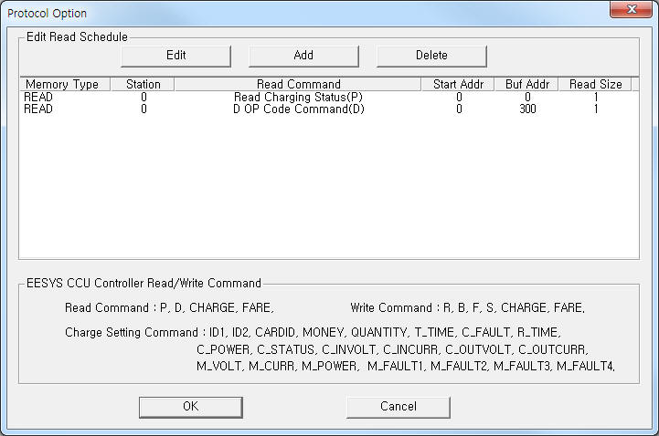 |
| <Figure 2> Example of EESYS CCU Controller communication driver’s Option dialogue box |
You can also set read schedule by using
![]() ,
,
![]() ,
,
![]() button and listbox of <Figure 2>.
button and listbox of <Figure 2>.
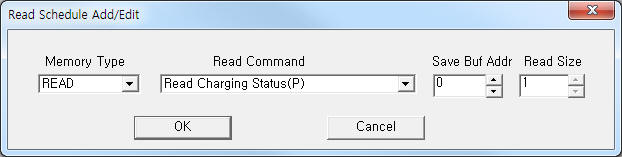 |
| <Figure 3> Example of EESYS CCU Controller communication driver’s read schedule Add/Edit dialogue box |
When you click Add button or Edit button in dialogue box of <Figure 2>, dialogue box of <Figure 3> will be shown.
You can set EESYS CCU controller by using write commands.
Bit write
Bit write and word write have the same setting parameters except output value(0 or 1).
Word write
Word write setting parameters are as follows:
1) PORT : Port no. (0 ~ 255)
2) STATION : Don't care.
3) ADDRESS : Write command = F, Extra2 = 1 : 0 = charging mode, 1 = load select, 2 = charging time, 3 = charging OFF time, 4 = discharging time, 5 = time unit, 6 = charging voltage, 7 = charging current, 8 = discharging current, 9 = reserved value select.
Write command = C_FAULT : 0 = CCU Fault, 1 = BSM Fault, 2 = BATT Fault 1, 3 = reserved, 4 = BATT fault 2 value select.
Write command = M_VOLT, M_CURR, M_POWER, M_FAULT1, M_FAULT2, M_FAULT3, M_FAULT4 : 0 ~ 9 selection of charger module number.
Other write command : Don't care.
4) EXTRA 1 : Write command = R, B, F, S, CHARGE, FARE, ID1, ID2, CARDID, MONEY, QUANTITY, T_TIME, C_FAULT, R_TIME, C_POWER, C_STATUS, C_INVOLT, C_INCURR, C_OUTVOLT, C_OUTCURR, M_VOLT, M_CURR, M_POWER, M_FAULT1, M_FAULT2, M_FAULT3, M_FAULT4. (Refer to <Table 2>)
5) EXTRA 2 : Write command = F : 1 = setting of charging plug connection status value(accoding to ADDRESS), 0 = send charging plug status value.
Other write command : Don't care.
<Table 2> is a description of write command and write value of EESYS CCU Controller communication driver.
| Write Command | Contents | Output value | Remarks |
| R | Setting of operation status | 0 = Stop, 1 = Run |
|
| B | Setting of charging plug connection status | Don't care | |
| F | Setting of charging plug connection status | Don't care | Extra2 = 1 ADDRESS = 0 ~ 9 (setting of status). (0 = charging mode, 1 = load select, 2 = charging time, 3 = charging OFF time, 4 = discharging time, 5 = time unit, 6 = charging voltage, 7 = charging current, 8 = discharging current, 9 = reserved value select.) |
| Extra2 = 0 send charging plug connection status(saved). |
|||
| S | Write of stand by charging | Don't care | |
| CHARGE | Write data of charger operation status to Server | Don't care | ID1, ID2, CARDID, MONEY, QUANTITY, T_TIME, C_FAULT, R_TIME, C_POWER,
C_STATUS, C_INVOLT, C_INCURR, C_OUTVOLT, C_OUTCURR, M_VOLT, M_CURR, M_POWER, M_FAULT1, M_FAULT2, M_FAULT3, M_FAULT4 Command = setting of charging operation status to memory, then use 'CHARGE' command. |
| FARE | Read of basic fare from Server | Don't care | Save data to memory according to 'read schedule' ((save too at invalid 'Read Command'( ' ; ' character insert )) |
| ID1 | Save City/Do ID value to internal memory(for 'CHARGE' write command) | 1 : Gyeonggi, 2 = Gangwon, .... | |
| ID2 | Save charger ID value to internal memory(for 'CHARGE' write command) | WORD unit | |
| CARDID | Save User ID value to internal memory(for 'CHARGE' write command) | Double WORD unit | |
| MONEY | Save charging amount to internal memory(for 'CHARGE' write command) | 5dight 10decimal | won |
| QUANTITY | Save charging quantity to internal memory(for 'CHARGE' write command) | 6dight 10decimal | W(Watt) |
| T_TIME | Save total charging time to internal memory(for 'CHARGE' write command) | WORD unit | sec unit |
| C_FAULT | Save CCU Fault, BSM Fault, BATT Fault 1, reserved, ATT Fault 2 to internal memory(for 'CHARGE' write command) |
BYTE unit | ADDRESS : saving data type 0 = CCU Fault, 1 = BSM Fault, 2 = BATT Fault 1, 3 = reserved, 4 = BATT Fault 2. |
| R_TIME | Save current charging remain time to internal memory(for 'CHARGE' write command) | WORD unit | sec unit |
| C_POWER | Save output power to internal memory(for 'CHARGE' write command) | 4dight 10decimal | saving value = input value(dot 1) x 10, KW unit |
| C_STATUS | Save charging status to internal memory(for 'CHARGE' write command) | BYTE unit | 0 = Ready, 1 = Run, 2 = Stop, 3 = Error |
| C_INVOLT | Save charging input voltage to internal memory(for 'CHARGE' write command) | 4dight 10decimal | saving value = input value(dot 1) x 10, V unit |
| C_INCURR | Save charging input current to internal memory(for 'CHARGE' write command) | 4dight 10decimal | saving value = input value(dot 1) x 10, A unit |
| C_OUTVOLT | Save charging output voltage to internal memory(for 'CHARGE' write command) | 4dight 10decimal | saving value = input value(dot 1) x 10, V unit |
| C_OUTCURR | Save charging output current to internal memory(for 'CHARGE' write command) | 4dight 10decimal | saving value = input value(dot 1) x 10, A unit |
| M_VOLT | Save charging module 1 ~ 10 output voltage to internal memory(for 'CHARGE' write command) | 4dight 10decimal | ADDRESS : 0 ~ 9 = charger module 1 ~ 10, saving value = input value(dot 1) x 10, V unit |
| M_CURR | Save cahrging module 1 ~ 10 output current to internal memory(for 'CHARGE' write command) | 4dight 10decimal | ADDRESS : 0 ~ 9 = charger module 1 ~ 10, saving value = input value(dot 1) x 10, A unit |
| M_POWER | Save charging module 1 ~ 10 output power to internal memory(for 'CHARGE' write command) | 4dight 10decimal | ADDRESS : 0 ~ 9 = charger module 1 ~ 10, saving value = input value(dot 1) x 10, KW unit |
| M_FAULT1 | Save charging module 1 ~ 10 Fault 1 to internal memory(for 'CHARGE' write command) | BYTE unit | ADDRESS : 0 ~ 9 = charger module 1 ~ 10, |
| M_FAULT2 | Save charging module 1 ~ 10 ault 2 to internal memory(for 'CHARGE' write command) | BYTE unit | ADDRESS : 0 ~ 9 = charger module 1 ~ 10, |
| M_FAULT3 | Save charging module 1 ~ 10 ault 3 to internal memory(for 'CHARGE' write command) | BYTE unit | ADDRESS : 0 ~ 9 = charger module 1 ~ 10, |
| M_FAULT4 | Save charging module 1 ~ 10 ault 4 to internal memory(for 'CHARGE' write command) | BYTE unit | ADDRESS : 0 ~ 9 = charger module 1 ~ 10, |
| <Table 2> write command and write value of EESYS CCU Controller communication driver | |||
Write example 1)
PORT:0, station:0, ADDRESS:0000, Extra1:R, Extra2 : 0
The setting parameter shown above is an example of write for operation status setting of EESYS CCU Controller connected with 0 port.
Write example 2)
PORT:0, station:0, ADDRESS:0000, Extra1:F, Extra2 : 1
The setting parameter shown above is an example of write for saving of charging mode value to internal memory(port = 0).
Write example 3)
PORT:0, station:0, ADDRESS:0002, Extra1:F, Extra2 : 1
The setting parameter shown above is an example of write for saving of charging time to internal memory(port = 0).
Write example 4)
PORT:0, station:0, ADDRESS:0000, Extra1:F, Extra 2: 0
The setting parameter shown above is an example of write for send charging plug connection status value(saved to internal memory) connected with 0 port.
Write example 5)
PORT:0, station:0, ADDRESS:0000, Extra1:FARE, Extra2 : 0
The setting parameter shown above is an example of write for read basic fare from Server and save readed data to memory(WORD, DWORD, FLOAT, DOUBLE, INT64).
Write example 6)
PORT:0, station:0, ADDRESS:0000, Extra1:MONEY, Extra2 : 0
The setting parameter shown above is an example of write for saving of charging amount to internal memory(port = 0).
(CHARGE Command = send saved data to Server)
Write example 7)
PORT:0, station:0, ADDRESS:0000, Extra1:CHARGE , Extra2 : 0
The setting parameter shown above is an example of write for charger operation status value(saved at internal memory) to Server.
(charger operation status value saving command = ID1, ID2, CARDID, MONEY, QUANTITY, T_TIME, ...)
Block write
EESYS CCU Controller communication driver don’t support ‘Block write’.
<Figure 4> shows the appearance of EESYS CCU Controller.
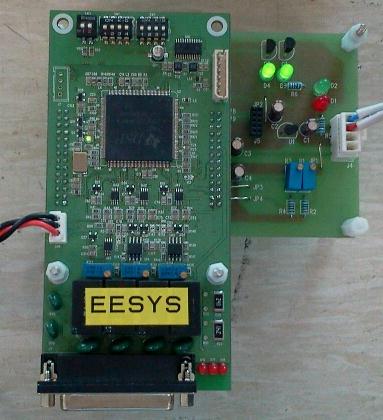 |
| <Figure 4> Appearance of EESYS CCU Controller |