E364xA Series DC-Power Supply communication driver is driver to communicate with DC-Power Supply of Agilent Technologies in U.S.A.
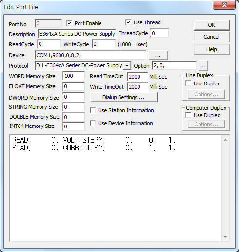
<Figure 1> is read setting example of E364xA Series DC-Power Supply communication driver.
|
|
| <Figure 1> Read setting example of E364xA Series DC-Power Supply communication driver |
Device part of <Figure 1> input Com Port(COM1), Baud Rate(9600), Parity Bit(0), Data Bit(8), Stop Bit(2) respectively, accordint to the setting of power supply.
In protocol option part, you can set termination code of protocol( 0 = LF, 1 = CR, 2 = CR + LF, default = 0 ), whether to check response code when write( 0 = don't check, 1 = check, default = 0). Each argument is a comma-delimited.
Read schedule of E364xA Series DC-Power Supply communication driver
Read schedule setting parameters are as follows:
1) Station – don't care.
2) Read command – APPLy?, VOLT?, VOLT:STEP?, CURR?, CURR:STEP?, ..... ( refer to <Table 1>)
3) Read start address – don't care.
4) Save start address for Communication Server – Saving start address of Communication Server.
5) Read size – fixed to 1.
Read schedule example)
READ, 0, VOLT:STEP?, 0, 0, 1,
READ, 0, CURR:STEP?, 0, 1, 1,
<Table 1> is read command contents of E364xA Series DC-Power Supply communication driver.
Read command |
Contents |
Data saving address |
Remarks |
APPLy? |
Read Voltage & Current |
Start addr + 0 : setting value of voltage Start addr + 1 : setting value of current |
|
VOLT? |
Read Voltage |
Start addr + 0 : setting value of voltage |
|
VOLT:STEP? |
Step Voltage |
Start addr + 0 : setting value of Step voltage |
|
CURR? |
Read Current |
Start addr + 0 : setting value of current |
|
CURR:STEP? |
Step Current |
Start addr + 0 : setting value of Step current |
|
MEAS:VOLT? |
Output Voltage |
Start addr + 0 : output value fo voltage |
|
MEAS:CURR? |
Output Current |
Start addr + 0 : output value fo current |
|
SYST:ERR? |
Read System Error |
Start addr + 0 : system error number Start addr + 1 : error message |
refet to STRING memory for error message |
| <Table 1> Read command contents of E364xA Series DC-Power Supply communication driver | |||
E364xA Series DC-Power Supply communication driver store the same data in WORD, DWORD, FLOAT, STRING memory, but the data format are different.
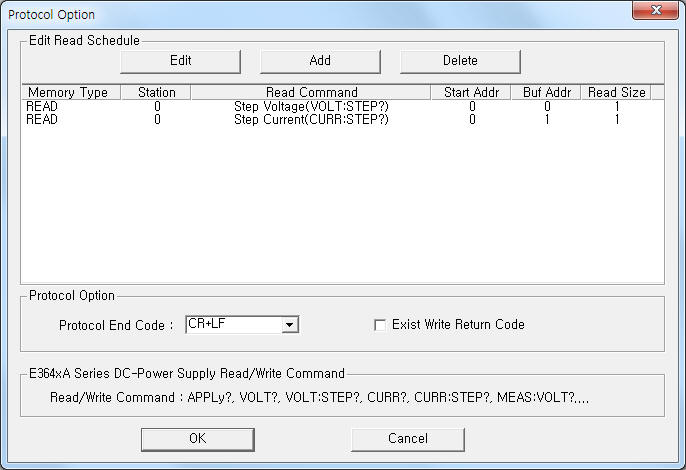
If you click the icon ![]() in protocol option part at
<Figure 1>, you
can see the dialog box such as <Figure 2>. you can also set read schedule by
using this part.
in protocol option part at
<Figure 1>, you
can see the dialog box such as <Figure 2>. you can also set read schedule by
using this part.
 |
|
<Figure 2> Example of E364xA Series DC-Power Supply communication driver’s Option dialog box |
You can set read schedule by using ![]() ,
, ![]() ,
, ![]() button and listbox of <Figure
2>.
button and listbox of <Figure
2>.
Also, you can set termination code of protocol, whether to check response code when write by using the part of ‘Protocol End Code’, ‘Exist Write Return Code’ shown in <Figure 2>.
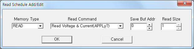 |
| <Figure 3> Example of E364xA Series DC-Power Supply communication driver’s read schedule Add/Edit dialog box |
When you click Add button or Edit button in dialogue box of <Figure 2>, dialogue box of <Figure 3> is shown.
You can set E364xA Series DC-Power Supply controller by using 'write settings'.
Digital Write
Digital write and analog write have the same setting parameters except output value.
Analog Write
Analog write setting parameters are as follows:
1) PORT Port no. (0 ~ 255)
2) STATION don't care.
3) ADDRESS data saving start address when read command. ( refer to <Table 1> )
4) Extra1 read/writte command.
refer to <Table 1> and user's manual of E364xA Series DC-Power Supply for more read/write command.
5) Extra2 don't care.
Write example 1)
PORT:0, station:0, ADDRESS:0100, Extra1:APPLy?, Extra2 : 0
The setting parameter shown above is read of Voltage & Current request example.
After reading, the readed data save at 100 ~ 101 WORD, DWORD, FLOAT, STRING memory.
Write example 2)
PORT:0, station:0, ADDRESS:0100, Extra1:VOLT:STEP 0.5, Extra2 : 0
The setting parameter shown above is Step Voltage setting example to 0.5. ( setting voltage = 0.5 V )
Note) Protocol of E364xA Series DC-Power Supply don't use response code after writing.
Therefore, you should check writing data by read Procedures.
Connection of communication cable and main power are as follows:
Connection of communication cable
Please connect normal RS-232C( or RS-485, Ethernet, ... ) communication cable to 9 pin connector of ODA DC-Power Supply Ex Series controller such as <Figure 4>.
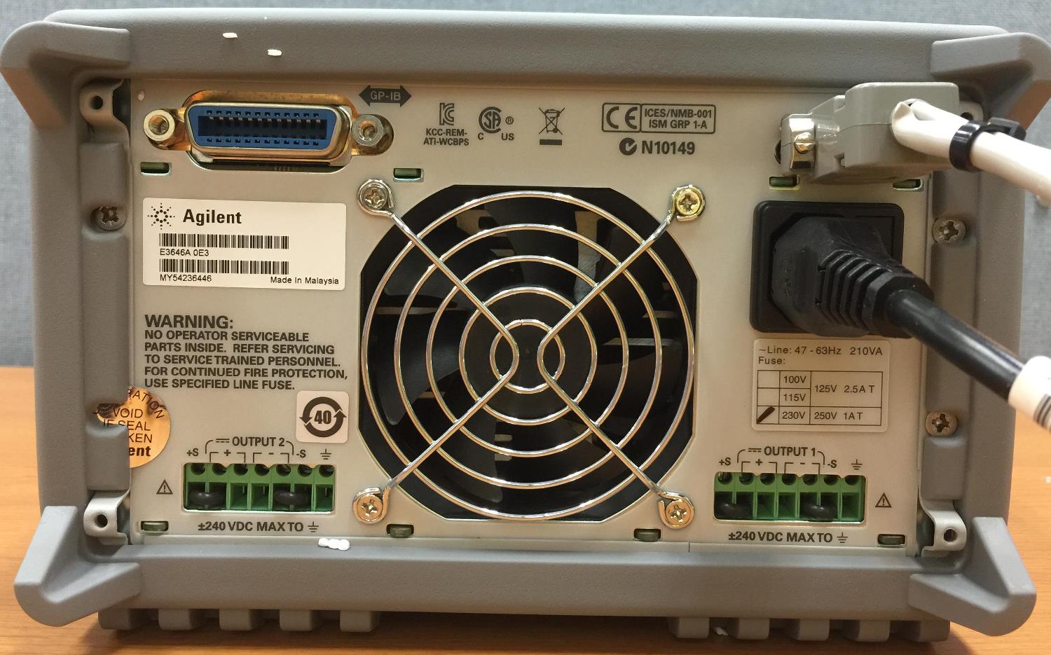 |
| <Figure 4> Connection example of main power and communication cable to E364xA Series DC-Power Supply controller |
Connection of main power
Please connect AC main power to power input connector such as <Figure 4>.
<Figure 5> shows the appearance of E364xA Series DC-Power Supply.
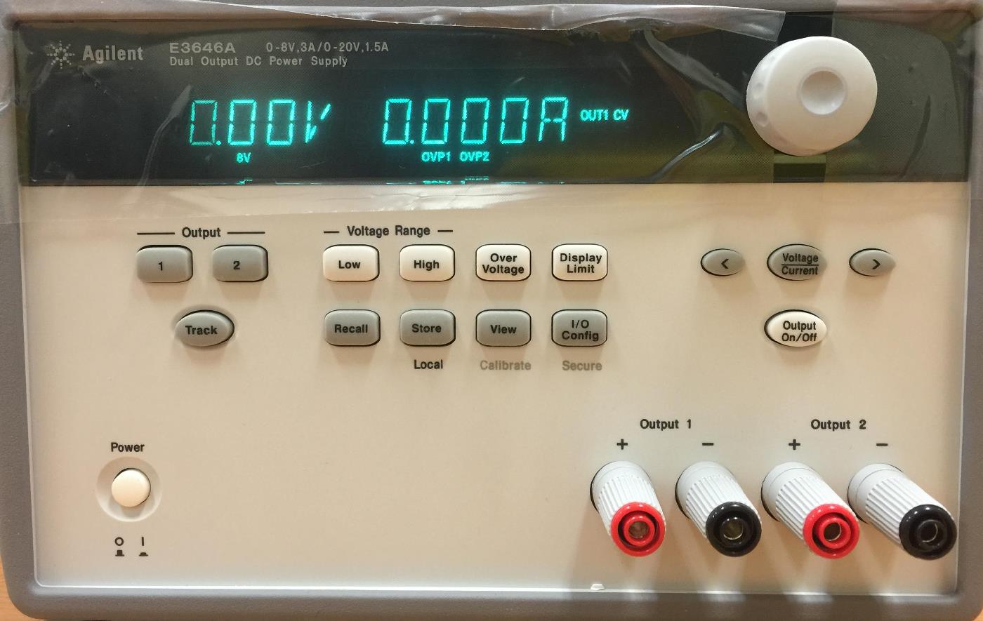 |
| <Figure 5> Appearance of E364xA Series DC-Power Supply |