Dynatronix DP/DPR Series communication driver is the driver to communicate with DC Power Supply of Dynatronix Inc. in U.S.A.
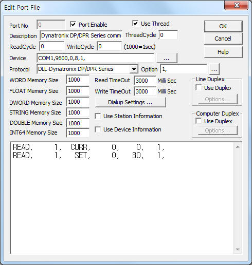
<Figure 1> is read setting example of Dynatronix DP/DPR Series communication driver.
|
|
| <Figure 1> Read setting example of Dynatronix DP/DPR Series communication driver |
Device part of <Figure 1> input Com Port(COM1), Baud Rate(9600), Parity Bit(0), Data Bit(8), Stop Bit(1) respectively, according to setting of controller.
In protocol option part, you can set whether to use and check CRC code( 1, use, 0 = don't use, default = 1)
Dynatronix DP/DPR Series communication driver read schedule
Read schedule setting parameters are as follows:
1) Unit address – 0 ~ 99 unit ID number. 0 = global, 1 ~ 99 = unit address.
2) Read command – command = CURR, SET.
CURR = read of current value,
SET = read setting value.
3) Read start address – 0 ~ 9 setting number when SET command.
4) Save start address for Communication Server – Saving start address of Communication Server.
5) Read size – fixed to 1. ( refer to <Table 1>, <Table 2> )
Read schedule example)
READ, 1, CURR, 0, 0, 1,
READ, 1, SET, 0, 30, 1,
<Table 1>, <Table 2> are data saving address and contents for CURR, SET read command.
| Data saving address | Contents | Remakrs |
| start addr + 0 | operate state | 0=standby, 1=operate, 2=pause, 3=inhibit, 4=trickle, 5=pause-trickle |
| start addr + 1 | active setup number | 0 ~ 10, 0=unsaved values |
| start addr + 2 | active recipe number | 0 ~ 8, 0=unsaved values |
| start addr + 3 | active recipe step | 1 ~ 8 |
| start addr + 4 | forward current | amps, float data |
| start addr + 5 | forward voltage | volts, float data |
| start addr + 6 | reverse current | amps, float data |
| start addr + 7 | reverse voltage | volts, float data |
| start addr + 8 | XTC mode | 0=manual, 1=ATC, 2=RTC (XTC means either ATC or RTC) |
| start addr + 9 | XTC reading | Amin/Ahr for ATC or Sec/Min/Hr for RTC, float data |
| start addr + 10 | forward totalizer | Amin/,Ahr, float data |
| start addr + 11 | reverse totalizer | Amin/Ahr, float data |
| start addr + 12 | ramp time reading | Sec/Min, float data |
| start addr + 13 | forward ramp active level setting | peak amps/volts |
| start addr + 14 | reverse ramp active level setting | |
| start addr + 15 | relay atc left | Amin/Ahr, float data |
| start addr + 16 | relay on time left | minutes |
| start addr + 17 | alarm flag | 1=read the Alarm command to determine which alarm or error |
| start addr + 18 | active setup changed flag | 0 = no change, 1 = changed |
| start addr + 19 | active recipe changed flag | |
| start addr + 20 | recipe step 1’s ‘step run count | optional |
| start addr + 21 | recipe step n’s ‘step run count | |
| <Table 1> Data saving address and contents for CURR read command | ||
| Data saving address | Contents | Remakrs |
| start addr + 0 | setup number | w0=active, 1-10=saved |
| start addr + 1 | regulation mode | 0=current, 1=crossover, 2=voltage |
| start addr + 2 | forward current setting | amps, float data |
| start addr + 3 | forward voltage setting | volts, float data |
| start addr + 4 | reverse current setting | amps, float data |
| start addr + 5 | reverse voltage setting | volts, float data |
| start addr + 6 | current tolerance | % of setting, 0=disabled |
| start addr + 7 | voltage tolerance | |
| start addr + 8 | fwd/rev timing resolution index | pulse units : 0=xx.xx ms, 1=xxx.x ms, 2=x.xxx s, 3=xx.xx s CRSR or DCR units : 0=xxxx sec, xxxx min |
| start addr + 9 | on/off timing resolution index | 0=xx.xx ms, 1=xxx.x ms, 2=x.xxx s, 3=xx.xx s |
| start addr + 10 | forward duration | mSec or Sec, float data |
| start addr + 11 | forward on time | |
| start addr + 12 | forward off time | |
| start addr + 13 | reverse duration | |
| start addr + 14 | reverse on time | |
| start addr + 15 | reverse off time | |
| start addr + 16 | RTC timing resolution index | 0=xxx.x sec, 1=xxxx sec, 2=xx.xx min, 3=xxx.x min, 4=xxxx min, 5=xx.xx hr, 6=xxx.x hr |
| start addr + 17 | ATC amp-time resolution index | 0=x.xxx amp-min, 1=xx.xx amp-min, 2=xxx.x amp-min, 3=xxxx amp-min, 4=x.xxx amp-hr, 5=xx.xx amp-hr, 6=xxx.x amp-hr, 7=xxxx amp-hr |
| start addr + 18 | XTC mode | 0=manual, 1=ATC, 2=RTC |
| start addr + 19 | XTC preset | Amin/Ahr or Sec/Min/Hr, limited by RTC/ATC resolution index above, float data |
| start addr + 20 | ATC accumulation mode | 0=forward, 1=forward-reverse |
| start addr + 21 | totalizer resolution index | 0=x.xxx amp-min, 1=xx.xx amp-min, 2=xxx.x, amp-min, 3=xxxx amp-min, 4=x.xxx amp-hr, 5=xx.xx amp-hr, 6=xxx.x, amp-hr, 7=xxxx amp-hr |
| start addr + 22 | relay amp-time preset | Amin/Ahr, float data |
| start addr + 23 | relay on-time | minutes |
| start addr + 24 | ramp time resolution index | 0=xxxx sec, 1=xxxx min |
| start addr + 25 | ramp mode | 0=disable, 1=up, 2=down |
| start addr + 26 | ramp duration | Sec/Min |
| start addr + 27 | ramp start offset | percent of signal setting, 0=minimum, 99=maximum |
| start addr + 28 | trickle flag | 0=disable, 1=enable |
| start addr + 29 | trickle level | percent of forward current setting |
| start addr + 30 | end-of-cycle alarm enable | 0=disable, 1=enable |
| start addr + 31 | current error alarm enable | |
| start addr + 32 | voltage error alarm enable | |
| start addr + 33 | “relay on” alarm enable | |
| <Table 2> Data saving address and contents for SET read command | ||
Dynatronix DP/DPR Series communication driver store the same data in WORD, DWORD, FLOAT, DOUBLE memory, but the data format are different.
If you click the icon ![]() in protocol option part at
<Figure 1>, you
can see the dialog box such as <Figure 2>. you can also set read schedule by
using this part.
in protocol option part at
<Figure 1>, you
can see the dialog box such as <Figure 2>. you can also set read schedule by
using this part.
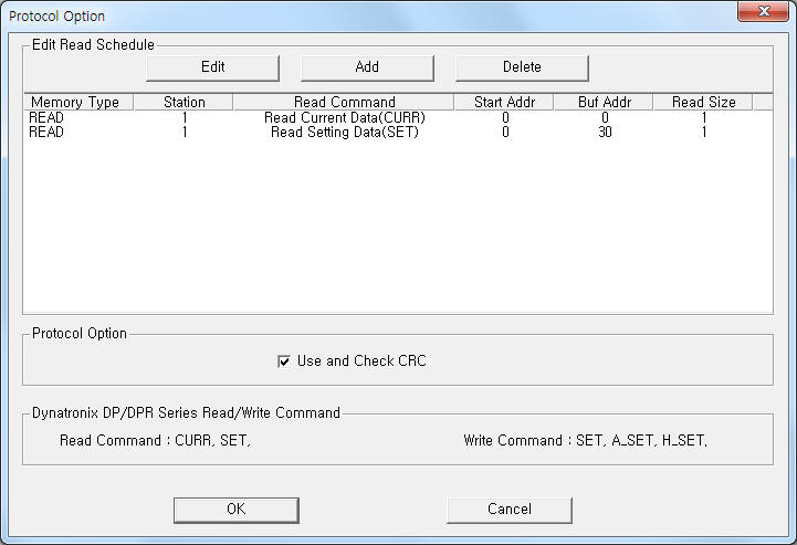 |
| <Figure 2> Example of Dynatronix DP/DPR Series communication driver’s Option dialog box |
You can set read schedule by using ![]() ,
, ![]() ,
, ![]() button and listbox of <Figure
2>.
button and listbox of <Figure
2>.
Also, you can setwhether to use and check CRC code by using the part of ‘Use and Check CRC’ shown in <Figure 2>.
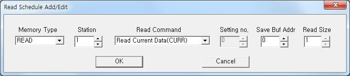 |
| <Figure 3> Example of Dynatronix DP/DPR Series communication driver’s read schedule Add/Edit dialog box |
When you click Add button or Edit button in dialogue box of <Figure 2>, dialogue box of <Figure 3> is shown.
You can set Dynatronix DP/DPR Series controller by using 'write settings'.
Digital Write
Digital write and analog write have the same setting parameters except output value.
Analog Write
Analog write setting parameters are as follows:
1) PORT Port no. (0 ~ 255)
2) STATION 0 ~ 99 unit ID number. 0 = global, 1 ~ 99 = unit address.
3) ADDRESS 0 ~ 32 writing contents when SET write command. ( refer to <Table 3> )
4) Extra1 writte command = SET, A_SET, H_SET.
SET : writing of setting value, ( refer to <Table 3> )
A_SET : writing of activated 'setup' number, ( Output value : 0 ~ 10 setup number )
H_SET : changing of communication mode. ( Output value : 0=panel, 1=host, 2=analog, 3=panel-analog, 4=host-analog )
5) Extra2 0 ~ 10 'setup' number when SET write command.
Note) You can write 'setting value', ... when communication mode = 'Host.
Also, 1 ~ 9 setup number can only use the device that installed 'flash' memory.
<Table 3> is setting parameters for SET write command.
| Address value | Contents | Output value |
| 0 | regulation mode | 0=current, 1=crossover, 2=voltage |
| 1 | forward current setting | float value |
| 2 | forward voltage setting | |
| 3 | reverse current setting | |
| 4 | reverse voltage setting | |
| 5 | current tolerance | 0 ~ 100, 0=disabled |
| 6 | voltage tolerance | |
| 7 | fwd/rev timing resolution index | pulse units : 0=xx.xx ms, 1=xxx.x ms, 2=x.xxx s, 3=xx.xx s CRSR or DCR units : 0=xxxx sec, xxxx min |
| 8 | on/off timing resolution index | 0=xx.xx ms, 1=xxx.x ms, 2=x.xxx s, 3=xx.xx s |
| 9 | forward duration | float value |
| 10 | forward on time | |
| 11 | forward off time | |
| 12 | reverse duration | |
| 13 | reverse on time | |
| 14 | reverse off time | |
| 15 | RTC timing resolution index | 0=xxx.x sec, 1=xxxx sec, 2=xx.xx min, 3=xxx.x min, 4=xxxx min, 5=xx.xx hr, 6=xxx.x hr |
| 16 | ATC amp-time resolution index | 0=x.xxx amp-min, 1=xx.xx amp-min, 2=xxx.x amp-min, 3=xxxx amp-min, 4=x.xxx amp-hr, 5=xx.xx amp-hr, 6=xxx.x amp-hr, 7=xxxx amp-hr |
| 17 | XTC mode | 0=manual, 1=ATC, 2=RTC |
| 18 | XTC preset | float value |
| 19 | ATC accumulation mode | 0=forward, 1=forward-reverse |
| 20 | totalizer resolution index | 0=x.xxx amp-min, 1=xx.xx amp-min, 2=xxx.x, amp-min, 3=xxxx amp-min, 4=x.xxx amp-hr, 5=xx.xx amp-hr, 6=xxx.x, amp-hr, 7=xxxx amp-hr |
| 21 | relay amp-time preset | float value |
| 22 | relay on-time | integer value |
| 23 | ramp time resolution index | 0=xxxx sec, 1=xxxx min |
| 24 | ramp mode | 0=disable, 1=up, 2=down |
| 25 | ramp duration | nteger value |
| 26 | ramp start offset | 0 ~ 99, 0=minimum, 99=maximum |
| 27 | trickle flag | 0=disable, 1=enable |
| 28 | trickle level | 0 ~ 100 |
| 29 | end-of-cycle alarm enable | 0=disable, 1=enable |
| 30 | current error alarm enable | |
| 31 | voltage error alarm enable | |
| 32 | “relay on” alarm enable | |
| <Table 3> Setting parameters for SET write command | ||
Write example 1)
PORT:0, station:1, ADDRESS:0000, Extra1:SET, Extra2 : 0
The setting parameter shown above is regulation mode setting example of unit ID 1 Dynatronix DP/DPR Series controller.
Write example 2)
PORT:0, station:1, ADDRESS:0001, Extra1:SET, Extra2 : 0
The setting parameter shown above is forward current value setting example of unit ID 1 Dynatronix DP/DPR Series controller.
Write example 3)
PORT:0, station:1, ADDRESS:0000, Extra1:H_SET, Extra2 : 0, Output value = 1
The setting parameter shown above is changing to 'Host' mode setting example of unit ID 1 Dynatronix DP/DPR Series controller.
Block Write
Dynatronix DP/DPR Series communication driver don't support 'Block Write'.