Data Send from Master Communication Driver is the driver in order to transmit the specific data to electronic display board.
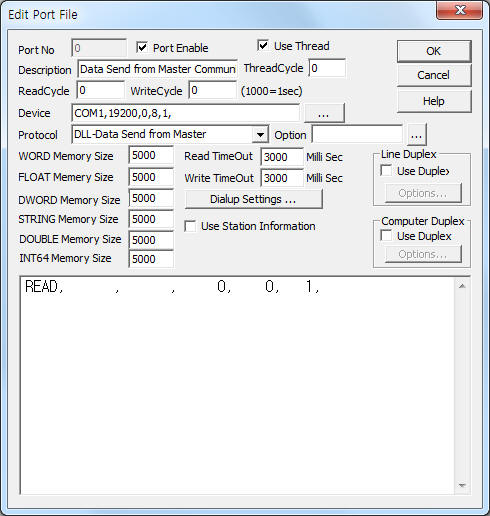
<Figure 1> is read setting example of Data Send from Master communication driver.
 |
| <Figure 1> Read setting example of Data Send from Master communication driver |
Device part of <Figure 1> input Com Port(COM1), Baud Rate(19200), Parity Bit(0), Data Bit(8), Stop Bit(1) respectively, according to master equipment.
Data Send from Master communication driverí»s read schedule
Data Send from Master communication driver's read schedule input 'READ' one line.
Read schedule example)
READ, , , 0, 0, 1,
You can transmit the specific data to DPM by using write settings.
Bit Write
Bit write and word write have the same setting parameters except output value.( 0 or 1 )
Word Write
Word write setting parameters are as follows:
1) PORT Port no. (0 ~ 255)
2) STATION Writing item of DATA or E3 command. 1 = water level(cm unit), 2 = current output(W unit), 3 = annul accumulate power(W unit), 4 = total accumulate power(W unit),
Other command = don't care.
3) ADDRESS Data saving address(WORD, DWORD, FLOAT memory) of writed value.
4) Extra1 Write command.
ONOFF or 16 : electronic display board On/Off command, ( writing value = 0 or 1 )
LED or 1A : electronic display board 'bright' setting command, ( writing value = 0 ~ 255 )
DATA or E3 : electronic display board 'data' setting command, ( writing value = double word data )
5) Extra2 Writing color of DATA or E3 command. 1 = G(green), 2 = Y(yellow), 0, 3, ... = R(red),
Other command = don't care.
Write example 1)
PORT : 0 STATION : 0 ADDRESS : 0000 EXTRA1 : ONOFF EXTRA2 :
The setting parameter shown above is an example of 'On/Off' control at current connected electronic display board.
After write, the writed data save '0 WORD, DWORD, FLOAT' memory.
Write example 2)
PORT : 0 STATION : 0 ADDRESS : 0001 EXTRA1 : LED EXTRA2 :
The setting parameter shown above is an example of 'bright' setting at current connected electronic display board.
After write, the writed data save '1 WORD, DWORD, FLOAT' memory.
Write example 3)
PORT : 0 STATION : 1 ADDRESS : 0002 EXTRA1 : DATA EXTRA2 : 0
The setting parameter shown above is an example of water level 'data' setting with 'red' color.
After write, the writed data save '2 WORD, DWORD, FLOAT' memory.
Write example 4)
PORT : 0 STATION : 2 ADDRESS : 0003 EXTRA1 : DATA EXTRA2 : 0
The setting parameter shown above is an example of current output 'data' setting with 'red' color.
After write, the writed data save '3 WORD, DWORD, FLOAT' memory.
Write example 5)
PORT : 0 STATION : 3 ADDRESS : 0004 EXTRA1 : DATA EXTRA2 : 1
The setting parameter shown above is an example of annul accumulate power 'data' setting with 'green' color.
After write, the writed data save '4 WORD, DWORD, FLOAT' memory.
Write example 6)
PORT : 0 STATION : 4 ADDRESS : 0005 EXTRA1 : DATA EXTRA2 : 2
The setting parameter shown above is an example of total accumulate power 'data' setting with 'yellow' color.
After write, the writed data save '5 WORD, DWORD, FLOAT' memory.