DNP KEPCO10 Communication Driver is the driver to communicate with DNP3.0 protocol.
Note) DNP KEPCO10 communication driver can use only one driver at one device.
If you want to use twor or more driver at multi device, you can use DNP KEPCO10 Add 01 ~ DNP KEPCO10 Add 16 driver. ( max = 17 driver)
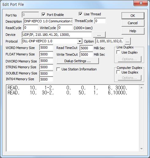
<Figure 1> is read setting example of DNP KEPCO10 communication driver.
|
|
| <Figure 1> Read setting example of DNP KEPCO10 communication driver |
Device Setting of <Figure 1> are input, device type( UDP/IP ), IP address of DNP controller( 210.180.41.20 ), service port address( 13000 )respectively, according to setting of controller.
Read Cycle of DNP KEPCO10 communication driver should alway be set to 0.
Read/Write TimeOut can be set to more than 5,000 mSec( 5 second ).
Also DNP source address(0 ~ 65534, default = 2), alarm number when accur SOE ( Class 1 ) Data(0 ~ 999, default = 100), alarm number when accur COS ( Class 2 ) Data(0 ~ 999, default = 101), alarm number when accur Class 3 Data(0 ~ 999, default = 102), whether to save the alarm data of Class(0 = do not save, 1 = save, default = 0), memory saving type of accurred SOE(WORD, DWORD, FLOAT, default = DWORD), memory saving start address of accurred SOE(0 ~ 9999, defalut = 0), memory saving type of accurred COS(WORD, DWORD, FLOAT, default = DWORD), memory saving start address of accurred COS(0 ~ 9999, defalut = 0), memory saving type of accurred Class 3(WORD, DWORD, FLOAT, default = DWORD), memory saving start address of accurred Class 3(0 ~ 9999, defalut = 0) are set by using option part (separated by commas each parameter).
DNP KEPCO10 communication driver’s read schedule
Read schedule setting parameters are as follows:
1) Station – DNP controller station number = 0 ~ 65534.
2) Read Command – Read Object-Variation. ( Refer to <Table 1> )
ex) 1-1, 1-2, … 30-1, 30-2, … 50-1, …
3) Read Start Address – Read start address of each Object, Variation. ( if Qualifier field = 06, 07, 08 - don't care )
Qualifier – 00, 01 : read start address,
Qualifier – 06, 07, 08 : don't care.
4) Save start address for Communication Server – Saving start address of Communication Server.
5) Read Size – Read size or end of each Object, Variation. ( if Qualifier field = 06 - don't care )
Qualifier – 00, 01 : read end address,
Qualifier – 07, 08 : read size ( 1 ~ ),
Qualifier – 06 : don't care.
6) Qualifier Field – Qualifier field of DNP protocol.
00, 01 : 8 bit, 16 bit Start/Stop,
07,08 : 8 bit, 16 bit Limited Quantity,
06, etc : read of all data. ( 06 or another number )
7) Read Period – Read period of each read schedule, 0 ~ 65535 mSec. (1000 mSec = 1 second )
Read schedule example)
READ, 10, 1-2, 0, 0, 1, 6, 3000,
READ, 10, 30-2, 0, 50, 1, 6, 10000,
<Table 1> is Object-Variation and readed data saving method of DNP KEPCO10 communication driver.
| Object-Variation | Contents | Readed data saving method | Remarks |
| 1-1 | Single Bit Binary Input | Save 1 bit data and status bit at 1 memory | |
| 1-2 | Binary Input with Status | ||
| 2-1 | Binary Input Change without Time | Save status 'Byte ' value ato 1 memory | COS( Class 2 ) |
| 2-2 | Binary Input Change with Time | Save status value,year, month, day, hour, minute, second, milli-second at 8 memory | SOE( Class 1 ) |
| 2-3 | Binary Input Chg with Relative Time | ||
| 10-2 | Binary Output Status | Save status 'Byte ' value ato 1 memory | |
| 12-1 | Control Relay Output Block | ||
| 20-1 | 32 bit Binary Counter | Save flag, DWORD/WORD value at 2 memory | |
| 20-2 | 16 bit Binary Counter | ||
| 20-5 | 32 bit Binary Counter without Flag | Save DWORD/WORD value at 1 memory | |
| 20-6 | 16 bit Binary Counter without Flag | ||
| 21-1 | 32 bit Frozen Counter | Save flag, DWORD/WORD counter value at 2 memory | |
| 21-2 | 16 bit Frozen Counter | ||
| 21-9 | 32 bit Frozen Counter without Flag | Save DWORD/WORD counter value at 1 memory | |
| 21-10 | 32 bit Frozen Counter without Flag | ||
| 22-1 | 32 bit Counter Change Event Without Time | Save flag, DWORD/WORD counter value at 2 memory | |
| 22-2 | 16 bit Counter Change Event Without Time | ||
| 22-5 | 32 bit Counter Change Event With Time | Save flag, DWORD/WORD counter value, year, month, day, hour, minute, second milli-second at 9 memory | |
| 22-6 | 16 bit Counter Change Event With Time | ||
| 23-1 | 32 bit Frozen Counter Event Without Time | Save flag, DWORD/WORD counter value at 2 memory | |
| 23-2 | 16 bit Frozen Counter Event Without Time | ||
| 23-5 | 32 bit Frozen Counter Event With Time | Save flag, DWORD/WORD counter value, year, month, day, hour, minute, second milli-second at 9 memory | |
| 23-6 | 32 bit Frozen Counter Event With Time | ||
| 30-1 | 32 bit Analog Input | Save flag, float(DWORD)/float(WORD) analog value at 2 memory | |
| 30-2 | 16 bit Analog Input | ||
| 30-3 | 32 bit Analog Input Without Flag | Save float(DWORD)/float(WORD) analog value at 1 memory | |
| 30-4 | 16 bit Analog Input Without Flag | ||
| 30-5 | short float Analog Input | Save flag, float(DWORD)/float(WORD) analog value at 2 memory | |
| 32-1 | 32 bit Analog Change Event Without Time | Save flag, float(DWORD)/float(WORD) analog value at 2 memory | |
| 32-2 | 16 bit Analog Change Event Without Time | ||
| 32-3 | 32 bit Analog Change Event with Time | Save flag, float(DWORD)/float(WORD) analog value, year, month, day, hour, minute, second, milli-second at 9 memory | |
| 32-4 | 16 bit Analog Change Event with Time | ||
| 40-1 | 32 bit Analog Output Status | Save flag, float(DWORD)/float(WORD) analog value at 2 memory | |
| 40-2 | 16 bit Analog Output Status | ||
| 40-3 | short float Analog Output Status | ||
| 41-1 | 32 bit Analog Output Block | ||
| 41-2 | 16 bit Analog Output Block | ||
| 41-3 | short float bit Analog Output Block | ||
| 50-1 | System Time and Date | Save year, month, day, hour, minute, second, milli-second at 7 memory | |
| 51-1 | Time and Date CTO | ||
| 51-2 | Unsynchronized Time and Date CTO | ||
| 60-1 | Class 0 (Class 1, 2, 3) Data | ||
| 60-2 | Class 1 Data | Response of Class data | 2-1 |
| 60-3 | Class 2 Data | 2-2 | |
| 60-4 | Class 3 Data | ||
| <Table 1> Object-Variation and readed data saving method of DNP KEPCO10 communication driver | |||
<Table 2>, <Table 3> are data saving address and contents of SOE, COS data.
Data Saving Address |
Contents |
Start Add + address(Point number) x 10 + 0 |
station number |
Start Add + address(Point number) x 10 + 1 |
Point number |
Start Add + address(Point number) x 10 + 2 |
status BYTE |
Start Add + address(Point number) x 10 + 3 |
year |
Start Add + address(Point number) x 10 + 4 |
month |
Start Add + address(Point number) x 10 + 5 |
day |
Start Add + address(Point number) x 10 + 6 |
hour |
Start Add + address(Point number) x 10 + 7 |
minute |
Start Add + address(Point number) x 10 + 8 |
second |
Start Add + address(Point number) x 10 + 9 |
milli-second |
| <Table 2> Data saving address and contents of SOE(Class 1) data | |
Data Saving Address |
Contents |
Start Add + address(Point number) x 3 + 0 |
station number |
Start Add + address(Point number) x 3 + 1 |
Point number |
Start Add + address(Point number) x 3 + 2 |
status값 BYTE |
| <Table 3> Data saving address and contents of COS ( Class 2 ) data | |
If you click the icon ![]() in protocol option part, you
can see the dialogue box such as <Figure 2>. you can also set read schedule by
using this part.
in protocol option part, you
can see the dialogue box such as <Figure 2>. you can also set read schedule by
using this part.
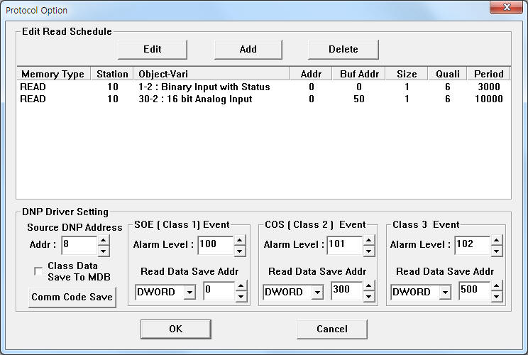 |
| <Figure 2> Example of DNP KEPCO10 communication driver’s Option dialogue box |
You can set read schedule by using ![]() ,
, ![]() ,
, ![]() button and listbox of <Figure
2>.
button and listbox of <Figure
2>.
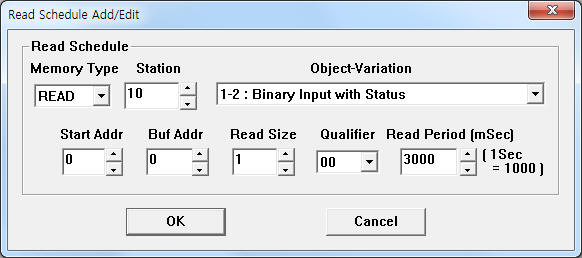 |
| <Figure 3> Example of DNP KEPCO10 communication driver’s read schedule Add/Edit dialogue box |
When you click Add button or Edit button in dialogue box of <Figure 2>, dialogue box of <Figure 3> is shown.
You can write the setting value by using write settings.
Bit Write
Bitd write setting parameters are as follows:
1) PORT Port no. (0 ~ 255)
2) STATION DNP controller station number = 0 ~ 65534.
3) ADDRESS Writing address. ( FILE_SAVE write command = don't care )
4) Extra1 Write command.
SELECT : 12-1 (Object-Variation ) Select digital outout command,
OPERATE : 12-1 (Object-Variation ) Operate digital output command,
DIRECT : 12-1 (Object-Variation ) Direct digital output command,
UNSOL : Unsolicated Message Enable/Disable output command,
FILE_SAVE : save/stop save command : current communication port send/receive data at 'work folder\SCAN\ COMM_CODE_%03d_%05d.txt ' file.
( %03d : PORT number, %05d : value of Extra2 )
etc : 12-1 (Object-Variation ) Select-Operate digital output command.
5) Extra2 FILE_SAVE write command = file number ( %05d ), other write command = Don't care.
Write example 1)
PORT : 0 STATION : 10 ADDRESS : 0000 EXTRA1 : 12-1 EXTRA2 :
The setting parameter shown above is an example of digital output(On/Off) of 0 digital address, 10 DNP station number.
Write example 2)
PORT : 0 STATION : 10 ADDRESS : 0005 EXTRA1 : 12-1 EXTRA2 :
The setting parameter shown above is an example of digital output(On/Off) of 5 digital address, 10 DNP station number.
Write example 3)
PORT : 0 STATION : 0 ADDRESS : 0000 EXTRA1 : FILE_SAVE EXTRA2 : 12, Output : On
The setting parameter shown above is an example of save current communication port send/receive code. Data saving file = work folder\SCAN\COMM_CODE_000_00012.txt, data type = Text.
Write example 4)
PORT : 0 STATION : 0 ADDRESS : 0000 EXTRA1 : FILE_SAVE EXTRA2 : 12. Output : Off
The setting parameter shown above is an example of stop save current communication port send/receive code. Data saving stop file = work folder\SCAN\COMM_CODE_000_00012.txt.
Bit Write
Bitd write setting parameters are as follows:
1) PORT Port no. (0 ~ 255)
2) STATION DNP controller station number = 0 ~ 65534.
3) ADDRESS Writing address. ( FILE_SAVE write command = don't care )
4) Extra1 Write command.
SELECT : 41-2 (Object-Variation ) Select analog output command,
OPERATE : 41-2 (Object-Variation ) Operate analog output command,
DIRECT : 41-2 (Object-Variation ) Direct analog output command,
UNSOL : Unsolicated Message Enable/Disable output command,
FILE_SAVE : save/stop save command : current communication port send/receive data at 'work folder\SCAN\ COMM_CODE_%03d_%05d.txt ' file.
( %03d : PORT number, %05d : value of Extra2 )
etc : 41-2 (Object-Variation ) Select-Operate analog output command.
5) Extra2 FILE_SAVE write command = file number ( %05d ), other write command = Don't care.
Write example 1)
PORT : 0 STATION : 10 ADDRESS : 0000 EXTRA1 : 41-2 EXTRA2 :
The setting parameter shown above is an example of analog output(Select and Operate) of 0 analog address, 10 DNP station number.
Write example 2)
PORT : 0 STATION : 10 ADDRESS : 0015 EXTRA1 : 41-2 EXTRA2 :
The setting parameter shown above is an example of analog output(Select and Operate) of 15( 16th ) analog address, 10 DNP station number.