CHINO KP Communication Driver is the driver to communicate with KP controller of CHINO Co., Ltd. in Japan.
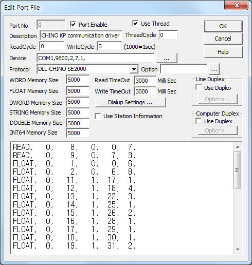
<Figure 1> is read setting example of CHINO KP communication driver.
|
|
| <Figure 1> Read setting example of CHINO KP communication driver |
Device part of <Figure 1> input Com Port(COM1), Baud Rate(9600), Parity Bit(2), Data Bit(7), Stop Bit(1) respectively.
CHINO KP controller can change baud rate, but parity bit, data bit, stop bit are fixed to 2, 7, 1.
CHINO KP communication driver’s read schedule
Read schedule setting parameters are as follows:
1) STATION – RS-232C : 0, RS-422 : 1~99.
2) Read command – Command = 1, 2, 8, 9, 11~25, 30~41 ( Refer to <Table 1>).
3) Read Start Address – Read start address.
4) Save start address for Communication Server – Saving start address of Communication Server.
5) Read Size – Fixed according to read command.
Read schedule example)
READ, 0, 8, 0, 0, 7,
READ, 0, 9, 0, 7, 3,
FLOAT, 0, 1, 0, 0, 6,
FLOAT, 0, 2, 0, 6, 8,
FLOAT, 0, 11, 1, 17, 1,
FLOAT, 0, 12, 1, 18, 4,
FLOAT, 0, 13, 1, 22, 3,
FLOAT, 0, 14, 1, 25, 1,
FLOAT, 0, 15, 1, 26, 2,
FLOAT, 0, 16, 1, 28, 1,
FLOAT, 0, 17, 1, 29, 1,
FLOAT, 0, 18, 1, 30, 1,
FLOAT, 0, 19, 1, 31, 2,
FLOAT, 0, 20, 1, 33, 2,
FLOAT, 0, 21, 1, 35, 1,
FLOAT, 0, 22, 1, 36, 1,
FLOAT, 0, 23, 1, 37, 3,
FLOAT, 0, 24, 1, 40, 1,
FLOAT, 0, 25, 1, 41, 1,
FLOAT, 0, 30, 1, 42, 2,
FLOAT, 0, 31, 1, 44, 1,
FLOAT, 0, 32, 1, 45, 2,
FLOAT, 0, 33, 1, 47, 1,
FLOAT, 0, 34, 1, 48, 1,
FLOAT, 0, 35, 1, 49, 2,
FLOAT, 0, 36, 1, 51, 1,
FLOAT, 0, 37, 1, 52, 1,
FLOAT, 0, 38, 1, 53, 3,
FLOAT, 0, 39, 1, 56, 1,
FLOAT, 0, 40, 1, 57, 1,
FLOAT, 0, 41, 1, 58, 1,
<Table 1> is read command and store values of CHINO KP communication driver.
| command contents | Command | Address | Read size(Fixed to 1) | Store values | Remarks |
| Real Data Request | 1 | don't care | 6 | 0 - Pv status | 0
=
1 = + 2= -Over Range |
| 1 – PV | |||||
| 2 – SV No | 1
~ 8 = SV No. 0 = Remote SV |
||||
| 3 – SV | |||||
| 4 – MV1 | |||||
| 5 – MV2 | |||||
| Execution Parameter Request |
2 | don't care | 8 | 0
– SV 1 – P 2 – I 3 – D 4 – AL1 5 – AL2 6 – AL3 7 – AL4 |
|
| Status
1 Request |
8 | don't care | 7 | 0
– Execution
No 1 – AL1 status 2 – AL2 status 3 – AL3 status 4 – AL4 status 5 – PV error status 6 – Hardware error |
( 1 ~ 8 ) |
| Status
2 Request |
9 | don't care | 3 | 0 – Auto/Man | 1=
Man 0 = Auto |
| 1 – A.T | 1
= AT 0 = Noraml |
||||
| 2 – Remote/Local | 1
= Remote 0 = Local |
||||
| SV | 11 | 1 ~ 8 | 1 | SV 값 | |
| Alarm | 12 | 1 ~ 8 | 4 | 0
– AL1 1 – AL2 2 – AL3 3 – AL4 |
|
| PID | 13 | 1 ~ 8 | 3 | 0
– P 1 – I 2 – D |
|
| Output Variables Limit | 14 | 1 ~ 8 | 1 | Output Variables Limit | |
| Output Higher/Lower Limit | 15 | 1 ~ 8 | 2 | 0
– Output L
Limit 1 – Output H Limit |
|
| Sensor Compensation | 16 | don't care | 1 | Sensor Compensation | |
| Digital Filter | 17 | don't care | 1 | Digital Filter | |
| Setting Value Variation Rate | 18 | don't care | 1 | Setting Value Variation Rate | |
| Remote Scaling | 19 | don't care | 2 | 0
– MIN 1 – MAX |
|
| Cascade | 20 | don't care | 2 | 0
– Cascade r 1 – Cascade b |
|
| Remote Shift | 21 | don't care | 1 | Remote Shift | |
| Remote Filter | 22 | don't care | 1 | Remote Filter | |
| Transmission
Type, Transmission Scale |
23 | don't care | 3 | 0 – type | 0 = SV, 1 = PV, 2 = MV |
| 1 – Trans Scale Min | |||||
| 2 – Trans Scale Max | |||||
| 2nd Output P | 24 | don't care | 1 | 2nd Output P | |
| 2nd Output Gap | 25 | don't care | 1 | 2nd Output Gap | |
| Measuring Input Unit | 30 | don't care | 2 | 0 – Input Type | |
| 1 –Unit | 0 = C, 1 = F, 2 = %, 3 = BL | ||||
| CJ INT/EXT | 31 | don't care | 1 | CJ INT/EXT | 0
= INT, 1 = EXT |
| Linear Scale | 32 | don't care | 2 | 0 – MIN1 – MAX | |
| PV Dot | 33 | don't care | 1 | ||
| Scale Dot | 34 | don't care | 1 | ||
| Alarm
Mode, Alarm Dead Band |
35 | 1 ~ 4 | 2 | 0 – Alarm Mode | 0
= DH, 1= DHW, 2 = DL, 3 = DLW, 4 = AH, 5 = |
| 1 – Blind Sector | |||||
| Dead Band | 36 | don't care | 1 | ||
| Pulse Cycle | 37 | don't care | 1 | ||
| FB Zero Span & Gain | 38 | don't care | 3 | 0 – Zero1 – Span2 – Gain | |
| Output Preset | 39 | don't care | 1 | ||
| Pv Error Output | 40 | don't care | 1 | ||
| Output
Direct / Reverse |
41 | don't care | 1 | 0
= Direct 1 = Reverse |
|
| <Table 1> Read command and store values of CHINO KP communication driver | |||||
You can set CHINO KP controller by using write settings.
Bit Write
Bit write setting parameters are as follows:
1) PORT Port no. (0 ~ 255)
2) STATION RS-232C : 0, RS-422 : 1~99.
3) ADDRESS Number of execution : 0 = all(1 ~ 8) or 1 ~ 8.
4) Extra1 Parameter number = 1~5, 11~25, 30~41.
5) Extra2 Memory number.
Write example 1)
Port:0, Station:0, Address : 0000, Extra1:1, Extra2:0
The setting parameter shown above is an example of write for AUTO/MAX selection of CHINO KP 0 station.
Word Write
Word write setting parameters are as follows:
1) PORT Port no. (0 ~ 255)
2) STATION RS-232C : 0, RS-422 : 1~99.
3) ADDRESS Number of execution : 0 = all(1 ~ 8) or 1 ~ 8.
4) Extra1 Parameter number = 1~5, 11~25, 30~41 ( Refer to <Table 1> ).
5) Extra2 Memory number.
Write example 1)
Port:0, Station:0, Address : 0000, Extra1:11, Extra2:0
The setting parameter shown above is an example of write for 'SV' value of CHINO KP 0 station.