CI-5010A Indicator Communication Driver is the driver to communicate with weighing indicator CI-5010A series controller of CAS in Korea.
Note) CAS CI-5010A INDICATOR controller has 4 type communication mode. You have to set proper communication mode.
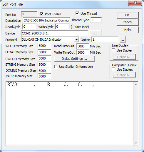
<Figure 1> is read setting example of CI-5010A Indicator communication driver.
 |
| <Figure 1> Read setting example of CI-5010A Indicator communication driver |
Device part of <Figure 1> input Com Port(COM1), Baud Rate(9600), Parity Bit(0), Data Bit(8), Stop Bit(1) respectively.
Also input read request communication mode( 0 : normal mode, 1 : data request mode , default = 0 ) by using option part.
Note) CAS CI-5010A INDICATOR controller can set baud rate 1200 ~ 19200bps by using front panel.
CI-5010A Indicator communication driver¡¯s read schedule
Read schedule setting parameters are as follows:
1) STATION – Data request mode = 0 ~ 99,
normal mode = Don't care.
2) Read command – Don't care.
3) Read start address – Don't care.
4) Save start address for Communication Server – Saving start address of Communication Server.
5) Read Size – Size = Fix to 1. ( Refer to <Table 1> )
Read schedule example)
READ, 1, S, 0, 0, 1,
<Table 1> is a description of store values and contents of CAS CI-5010A INDICATOR communication driver.
Store Values |
Contents |
Remarks |
Start Addr + 0 |
Controller status |
0 = ST ( stable ) 1 = US ( unstable ) 2 = OL ( overload ) 3 = other status |
Start Addr + 1 |
Weighing measurement type |
0 = GS ( gross weight ) 1 = NT ( net weight ) |
Start Addr + 2 |
Controller station number |
0 ~ 99 |
Start Addr + 3 |
Lamp status |
7 bit = 1 6 bit = stable 5 bit = 1 4 bit = hold 3 bit = printing 2 bit = gross weight 1 bit = container 0 bit = zero |
Start Addr + 4 |
Weighing value |
2 deciman point |
| <Table 1> Store values and contents of CAS CI-5010A INDICATOR communication driver | ||
If you click the icon
![]() in protocol
option part, you can see the dialogue box such as <Figure 2>. you can also set
read schedule by using this part.
in protocol
option part, you can see the dialogue box such as <Figure 2>. you can also set
read schedule by using this part.
 |
| <Figure 2> Example of CAS CI-5010A INDICATOR communication driver¡¯s Option dialogue box |
You can set read schedule by using
![]() ,
,
![]() ,
,
![]() button and listbox
of <Figure 2>.
button and listbox
of <Figure 2>.
¡®Request Comm Mode¡¯ can set at <Figure 4>.
 |
| <Figure 3> Example of CAS CI-5010A INDICATOR communication driver¡¯s read schedule Add/Edit dialogue box |
When you click Add button or Edit button in dialogue box of <Figure 2>, dialogue box of <Figure 3> is shown.
CAS CI-5010A INDICATOR communication driver don't support writing settings.
The setting of CAS CI-5010A INDICATOR are as follows.
Connection of serial communication cable
Please connect serial(RS-232C) communication calbe to rear of controller such as <Figure 4>.
 |
| <Figure 4> Example of CAS CI-5010A INDICATOR rear panel |
Connection of Load Cell sensor
Please connect Load Cell sensor to 'LOADCELL' connector that is provided when you purchased. ( Refer to <Figure 4> )
Setting of station
The setting of station is as follows.
1) Press 2 ( Hold ) button while 2 seconds or more.
2) Press 2( Hold ) and 4( Sum ) at the same time.
3) Input controller's station numbet to 0 ~ 99.
4) Press 'Setting'(PINK color button) button 2 times.
Setting of baud rate
The setting of baud rate is as follows.
1) Press 2 ( Hold ) button while 2 seconds or more.
2) Press 1( Zero ) and 4( Sum ) at the same time.
3) Set baud rate to 0, ( 1200 ), 1 ( 4800 ), 2 ( 9600 ), 3 ( 19200 ).
4) Press 'Setting'(PINK color button) button 2 times.
Setting of communication mode
The setting of communication mode is as follows.
1) Press 2 ( Hold ) button while 2 seconds or more.
2) Press 0( Time ) and 9( Container ) at the same time.
3) Set communication mode to 0, ( don't communicate ), 1 ( send data when stable, unstable ), 2 ( send data only stable status ), 3 ( send data only read request ).
4) Press 'Setting'(PINK color button) button 2 times.
 |
| <Figure 5> Appearance of CAS CI-5010A INDICATOR controller |