BAMS DC System communication driver is the driver to communicate with BAMS Server.
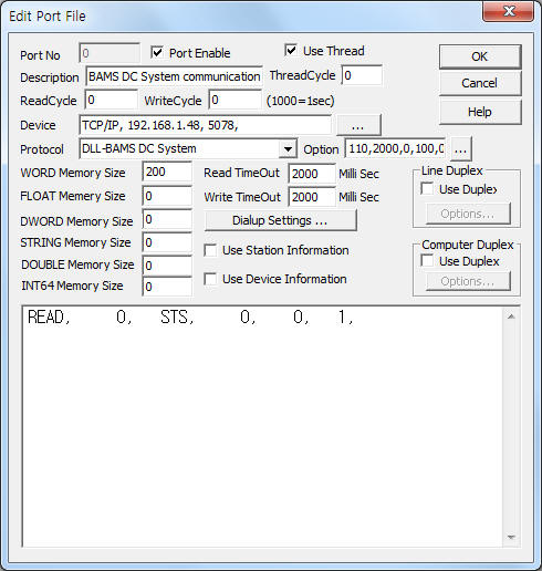
<Figure 1> is read setting example of BAMS DC System communication driver.
|
|
| <Figure 1> Read setting example of BAMS DC System communication driver |
Device part of <Figure 1> input Device Type(TCP/IP), IP address of PLC(192.168.1.48), service port number(5078) respectively, according to setting of server.
In protocol option part, you can set the following: user ID ( 0 ~ 65535, defalut = 110), sending interval for status monitoring data ( 0 ~ 65535 mSec, default = 2000 ), status monitoring data start address of DWORD memory ( 0 ~ 65535, default = 0 ), DC setting data start address of WORD memory ( 0 ~ 65535, default = 100 ), readed command and status data saving start address of WORD memory ( 0 ~ 65535, default = 0 ), main folder for report file( default = \Data ), weather to use auto-setting when DC setting Write command( 0 : use, 1 : don't use, default = 1 ). Each argument is a comma-delimited.
BAMS DC System communication driver read schedule
Read schedule setting parameters are as follows:
1) Station address – don't care.
2) Read command – command = fixed to STS.
3) Read start address – don't care.
4) Save start address for Communication Server – don't care.
5) Read Size – fixed to 1.
Read schedule example)
READ, 0, STS, 0, 0, 1,
<Table 1> is DWORD Memory address and contents for status monitoring data.
<Table 2> is WORD Memory address and contents for DC setting data.
<Table 3> is WORD Memory address and contents for command, status value of Server.
| Address ( DWORD ) |
Contents | Remarks |
| start address + 0 | current power of Demand | KW unit ( DWORD ) |
| start address + 1 | reference power of Demand | |
| start address + 2 | predictive power of Demand | |
| start address + 3 | target power of Demand | |
| start address + 4 | Demand Time | second unit ( word unit ) |
| start address + 5 | alarm status | normal : 7, 1 step : 6, 2 step : 4, Blocking : 0 |
| start address + 6 | number of load RMU | maximun = 32 |
| start address + 7 | load status of RMU |
DWORD (32 bit ) value, 1-32 = load status from low order bit ON : load |
| start address + 8 | communication status of RMU |
DWORD (32 bit ) value, 1-32 = communication status from low order bit OFF : normal, ON : Error |
| start address + 9 | current power of 1st RMU | W unit |
| start address + 10 | demand power of 1st RMU for 15minutes | |
| start address + 11 | 3phase accumulated power 1st RMU | KW unit |
| start address + 12 ~ 14 | 2nd RMU data | |
| ... | ... | |
| <Table 1> DWORD Memory address and contents for status monitoring data | ||
| Address (WORD) |
Contents | Remarks |
| start address + 0 | monitoring data sending interval to Server | WORD |
| start address + 1 ~ 4 | Server IP1 ~ 4 | 0 ~ 255 |
| start address + 5 | communication port number | WORD |
| start address + 6 | Local Monitoring communication speed | |
| start address + 7 | communication time out | BYTE |
| start address + 8 | DC ID | WORD |
| <Table 2> WORD Memory address and contents for DC setting data | ||
| Address (WORD) |
Contents | Remarks |
| start address + 0 | data sending count of status monitoring command | 0 ~ 65535 |
| start address + 1 | command flag | 1 = received command from Server, after control ( or other procedures ), set '0' |
| start address + 2 | control command for 1 ~ 16 load | 0 ~ 15bit = 1 ~ 16 load ( 1 : load ON ) |
| start address + 3 | control command for 17 ~ 32 load | 0 ~ 15bit = 17 ~ 32 load ( 1 : load ON ) |
| start address + 4 | release command for control prohibited flag | 1 = received release command from Server |
| start address + 5 | status value for control prohibited | 1 = enable control, 0 = control prohibited have to set control prohibited status, after control |
| start address + 6 | reserved control command flag | 1 = received reserved control command form Server |
| start address + 7 | start year for reserved control | 4 digit number |
| start address + 8 ~ 12 | start month, day, hour, minute, second for reserved control | 2 digit number |
| start address + 13 | end year for reserved control | 4 digit number |
| start address + 14 ~ 18 | end month, day, hour, minute, second for reserved control | 2 digit number |
| start address + 19 | type of control | 20h = total control, 21h = shift control 1, 22h =shift control 2 |
| start address + 20 | control interval | use only shift control 1, 2 |
| start address + 21 | returning interval | |
| start address + 22 | control cancel command flag | 1 = received control cancel command from Server |
| start address + 23 | day report command for power flag | 1 = received day report command from Server |
| start address + 24 | year of day report | 4 digit number |
| start address + 25 ~ 26 | month, day of day report | 2 digit number |
| start address + 27 | month report command for power flag | 1 = received month report command from Server |
| start address + 28 | year of month report | 4 digit number |
| start address + 29 | month of month report | 2 digit number |
| start address + 30 | event data command flag | 1 = received event data command from Server |
| start address + 31 | message command flag | 1 = received message command from Server save received message at STRING memory start address + 31 ~ |
| start address + 32 | DC setting Read command flag | 1 = received DC setting Read command from Server |
| start address + 33 | DC setting Write command flag | 1 = received DC setting Write command from Server |
| start address + 34 | monitoring data sending interval to Server | |
| start address + 35 ~ 38 | Server IP1 ~ 4 | |
| start address + 39 | communication port number | |
| start address + 40 | Local Monitoring communication speed | |
| start address + 41 | communication time out | |
| start address + 42 | DC ID | |
| start address + 43 | ACK confirm command flag | 1 = received ACK confirm command from Server |
| start address + 44 | time syncronization command flag | 1 = received time syncronization command from Server |
| start address + 45 | RMU day report command flag | 1 = received RMU day report command from Server |
| start address + 46 | year of RMU day report | 4 digit number |
| start address + 47 ~ 48 | month, day of RMU day report | 2 digit number |
| start address + 49 | RMU number | 1 ~ 32 RMU number |
| <Table 3> WORD Memory address and contents for command, status value fo Server | ||
<Table 4> is input method and filename for each report data.
| Data type | Filename and path | Input method | Contents |
| day report for power | main folder for report file\Day\%04d\%02d\%02d.dat ( %04d = year, %02d = month, %02d = day ) |
header 15 byte, flag 1byte, data value, data bcc ... ( 97 data ) ( hex-decimal ) |
target power of the day(kW), 15 minutes demend power (W) 1, 15 minutes demend power (W) 2, .... 15 minutes demend power (W) 96 |
| month report for power | main folder for report file\Month\%04d\%02d.dat ( %04d = year, %02d = month ) |
header 15 byte, flag 1byte, data value, data bcc ... ( 31 data ) ( hex-decimal ) |
amount of power for day (kWh) 1, amount of power for day (kWh) 2, .... amount of power for day (kWh) 31 |
| event data | main folder for report file\Event\Event_%02.dat ( %02d = 00 ~ 49 event event order number ) |
Separated by comma for each value. Input at 1st line. ( event data ) Use deciminalu unit data. |
year, month, day, hour, second, Event Code, Event Code |
| day report for RMU | main folder for report file\RMU\%04d\%02d\%02d\%02d.dat ( %04d = year, %02d = month, %02d = day, %02d = 1 ~ 32 RMU number ) |
header 15 byte, flag 1byte, data value, data bcc ... ( 96 data ) ( hex-decimal ) |
RMU
accumulated power 1, RMU accumulated power 2, .... RMU accumulated power 96 |
| <Table 4> Input method and filename for each report data | |||
If you click the icon
![]() in protocol option part, you can see the dialogue
box such as <Figure 2>. you can also set read schedule by using this part.
in protocol option part, you can see the dialogue
box such as <Figure 2>. you can also set read schedule by using this part.
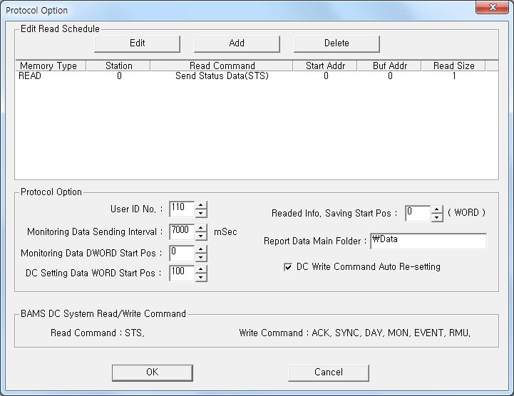 |
| <Figure 2> Example of BAMS DC System communication driver’s Option dialogue box |
You can also set read schedule by using
![]() ,
,
![]() ,
,
![]() button and listbox of <Figure 2>.
button and listbox of <Figure 2>.
Also, you can set user ID, sending interval for status monitoring data, status monitoring data start address of DWORD memory, DC setting data start address of WORD memory, readed command and status data saving start address of WORD memory, main folder for report file, weather to use auto-setting when DC setting Write command by using 'Protocol Option' part of <Figire 2>.
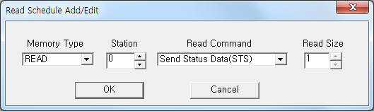 |
| <Figure 3> Example of BAMS DC System communication driver’s read schedule Add/Edit dialogue box |
When you click Add button or Edit button in dialogue box of <Figure 2>, dialogue box of <Figure 3> will be shown.
You can send ACK confirm, time syncronization command to Server by using write settings.
Digital write
Digital write and analog write have the same setting parameters except output value(0 or 1).
Analog write
Analog write setting parameters are as follows:
1) PORT port no. (0 ~ 255)
2) STATION data saving year when DAY, MON, RMU command.
3) ADDRESS data saving month or day when DAY, MON, RMU command.
DAY, RMU write command : higher 2 digit = month, lower 2 digit = day, ( 0527 : month = 05, day = 27 )
MON write command : data saving month.
4) EXTRA 1 write command = ACY, SYNC, DAY, MON, EVENT, RMU.
ACK : ACK confirm sending command to BAMS Server,
SYNC : time syncronization request command to BAMS Server.
DAY, MON, EVENT, RMU write command : data saving command for day, month, event, RMU day report request command from BAMS Server. ( data saving folder is 'main folder for report file' )
5) EXTRA 2 data saving contents when DAY, MON, EVENT, RMU command.
DAY : 0 ~ 95 = 15 minutes demand power, 100 = target power of the day,
MON : 1 ~ 31 = amount of power for each day( KWh ),
EVENT : 1 ~ 6 event code ( 1 = system error, 2 = BAMS server communication error, 3 = RMU RS-485 communication error, 4 = RMU control, 5 = RMU return(release control), 6 = RMU Fail ),
RMU : 0 ~ 95 = RMU accumulated power ( KWh, 24hour x 4 )
6) Output Value data saving contents when DAY, MON, EVENT, RMU write command.
DAY : 15 minutes demand power value or target power value of the day ( Extra2 = 100 ),
MON : amount of power value for each day( KWh ),
EVENT : event code data ( normally RMU ID ),
RMU : RMU accumulated power value ( KWh ).
Write example 1)
PORT:0, station:0, ADDRESS:0000, Extra1:ACK, Extra2 : 0
The setting parameter shown above is ACK confirm sending command to Server.
Write example 2)
PORT:0, station:0, ADDRESS:0000, Extra1:SYNC, Extra2 : 0
The setting parameter shown above is time syncronization request command to Server.
Write example 3)
PORT:0, station:2014, ADDRESS:0527, Extra1:DAY, Extra2 : 0
The setting parameter shown above is Day report data saving example for 1st 15 minutes demand power at 'main folder for report file'.
Write example 4)
PORT:0, station:2014, ADDRESS:0527, Extra1:DAY, Extra2 : 100
The setting parameter shown above is Day report data saving example for target power value of the day at 'main folder for report file'.
Write example 5)
PORT:0, station:2014, ADDRESS:005, Extra1:MON, Extra2 : 27
The setting parameter shown above is Month report data saving example. The saving data is amount of power value for 2014-05-27.