Autobase Open Bus driver is driver to communicate with Open Bus Slave controller of Autobase Inc. in Korea.
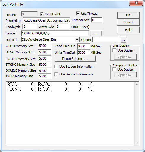
<Figure 1> is read setting example of Autobase Open Bus communication driver.
|
|
| <Figure 1> Read setting example of 'Autobase Open Bus' communication driver |
Device part of <Figure 1> input Com Port(COM8), Com Baud(9600), Parity Bit(0), Data Bit(8), Stop Bit(1) respectively, according to setting of Slave controller.
Autobase Open Bus communication driver's read schedule
Read schedule setting parameters are as follows:
1) Station – slave station number, 0 ~ 255.
2) Memory type and table number – xxnnn format. xx = memory type : RW, RD, RF, nnn = 0 ~ 255 table number.
RW : reading command for word memory, ( when set word memory at Slave controller )
RD : reading command for double word memory, ( when set double word memory at Slave controller )
RF : reading command for float memory, ( when set float memory at Slave controller )
RL : reading command for long( int 64 ) memory, ( when set long memory at Slave controller )
RU : reading command for double memory, ( when set double memory at Slave controller )
RT : reading command for text memory. ( when set text memory at Slave controller )
3) Address of table number – 0 ~ 65535.
4) Saving start address for Communication Server – Saving start address of Communication Server.
5) Reading size – The number of reading size at a time.
RW command : 1 ~ 240, RD, RF command = 1 ~ 120, RL, RU - 1 ~ 60.
Read schedule example)
READ, 0, RW000, 0, 0, 16
FLOAT, 0, RF001, 0, 0, 16
If you click the icon
![]() in protocol option part, you can see the dialogue
box such as <Figure 2>. you can also set read schedule by using this part.
in protocol option part, you can see the dialogue
box such as <Figure 2>. you can also set read schedule by using this part.
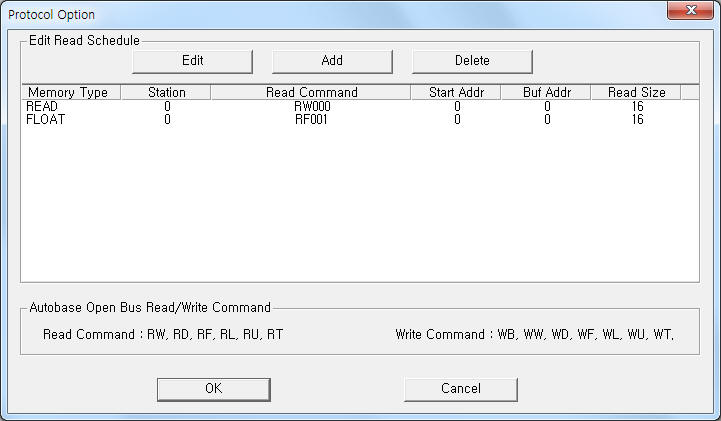 |
| <Figure 2> Example of Autobase Open Bus communication driver’s Option dialogue box |
You can also set read schedule by using
![]() ,
,
![]() ,
,
![]() button and listbox of <Figure 2>.
button and listbox of <Figure 2>.
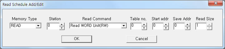 |
| <Figure 3> Example of Autobase Open Bus communication driver’s read schedule Add/Edit dialogue box |
When you click Add button or Edit button in dialogue box of <Figure 2>, dialogue box of <Figure 3> will be shown.
You can set the value of table( according to memory type ) by using write settings.
Digital write
Digital write and analog write have the same setting parameters except output value(0 or 1).
Analog write
Analog write setting parameters are as follows:
1) PORT port no. (0 ~ 255)
2) STATION slave station number, 0 ~ 255.
3) ADDRESS memory address of table number by decimal unit, 0 ~ 65535.
4) EXTRA1 xxnnn format memory type and table number, xx = memory type : RW, RD, RF, nnn = 0 ~ 255 table number.
WB : writing command by bit unit, ( when set word, double word memory at Slave controller )
WW : writing command by word unit, ( when set word memory at Slave controller )
WD : writing command by double word unit, ( when set double word memory at Slave controller )
WF : writing command by float unit, ( when set float memory at Slave controller )
WL : writing command by long( int 64 ) unit, ( when set long memory at Slave controller )
WU : writing command by double unit, ( when set double memory at Slave controller )
WT : writing command by text unit. ( when set text memory at Slave controller )
5) Extra2 bit position or STRING memory address when WB, WT write command.
WB write command : 0 ~ 15 or 0 ~ 31 bit position,
WT write command : 0 ~ 65535 STRING memory address to get the writing data.
Write example 1)
PORT:0, station:0, ADDRESS:0011, Extra1:WB000, Extra2 : 15
The setting parameter shown above is bit unit writing example for 15 bit( F bit ), 11 word(double word) address of 0 table number.
Write example 2)
PORT:0, station:0, ADDRESS:0011, Extra1:WW000, Extra2 : 0
The setting parameter shown above is word unit writing example for 11 word address of 0 table number.
Write example 3)
PORT:0, station:0, ADDRESS:0012, Extra1:WF001, Extra2 : 0
The setting parameter shown above is float unit writing example for 12 word address of 1 table number.
Write example 4)
PORT:0, station:0, ADDRESS:0021, Extra1:WT005, Extra2 : 30
The setting parameter shown above is text writing example for 21 text address of 5 table number.
The writing string data get from 30 STRING memory of Communication Server.
Note) You can set STRING memory by script at SCADA Server( for WT write command ).
type of script function) void @PlcScanWriteBlock(int port, int station, int address, string extra1, int extra2, object value, int array_size);
elements)
int port : port number,
int station : set to 0,
int address : address of STRING memory,
string extra1 : set to "#MEM#" ,
int extra2 : set to 3 ( STRING memory ),
object value : string data for writing,
int array_size : length of string, ( 80, ... ).
example 1) @PlcScanWriteBlock(0, 0, 20, "#MEM#", 3, "Test write output value 123", 80);
example 2) @PlcScanWriteBlock(0, 0, 20, "#MEM#", 3, $ST_0000, 80);
Block write
Autobase Open Bus communication driver don't support 'Block Write'.