Autobase Touch Smart I/O I communication driver is the driver to communicate with Smart I/O I equipment of Autobase Inc. in Korea.
Note) Autobase Touch Smart I/O I communication dirver use only Smart profram(CE OS).
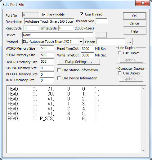
<Figure 1> is read setting example of Autobase Touch Smart I/O I communication driver.
|
|
| <Figure 1> Read setting example of Autobase Touch Smart I/O I communication driver |
Please input 'None' at Device part.
Autobase Touch Smart I/O I communication driver read schedule
Read schedule setting parameters are as follows:
1) Station address – don't care.
2) Read cmmand – command = DI, DO, AI, D_EN, P_STS, P_ON, P_MODE, P_INV, P_CLK, P_LOOP, P_PSTN, P_REG. ( refer to <Table 1> )
3) Read channel number – channel number. ( refer to <Table 1> )
DI, DO, P_STS, P_ON, P_INV read command = don't care.
4) Save start address for Communication Server – Saving start address of Communication Server.
5) Read Size – fixed to 1. ( refer to <table 1> )
Read schedule example)
READ, 0, DI, 0, 0, 1,
READ,
0, DO, 0, 1, 1,
READ, 0,
AI, 0, 2, 1,
READ, 0, AI, 1,
3, 1,
READ, 0, AI, 2, 4, 1,
READ, 0, AI, 3, 5, 1,
READ,
0, P_STS, 0, 6, 1,
<Table 1> is read command and contents of Autobase Touch Smart I/O I communication driver.
| Read command | Contents | Data saving address |
Channel number | Range |
| DI | read of digital input | start add + 0 : 0 ~ 7 DI On/Off status | don't care | 0 : Off, 1 : On can use input or output |
| DO | read of digital output | start add + 0 : 0 ~ 7 DO On/Off status | ||
| AI | read of analog input | start add + 0 : 0 ~ 4095( 12 bit ) analog value | 0 ~ 3 | 0 ~ 4095 |
| D_EN | output enable for DI, DO module | start add + 0 : 0 ~ 255 output enable value for DI, DO |
0 = DI, 1 = DO |
0 ~ 255 ( each bit ) 0 : input, 1 : output example) 0 = all input, 255 = all output |
| P_STS | read of PWM status | start add + 0 : PWM status value | don't care | 0 bit : PWM A status 1 bit : PWM B status 0 = normal, 1 = busy |
| P_ON | read of PWM Enable/Trig value | start add + 0 : PWM Enable/Trig status | 0 bit : PWM A Enable 1 bit : PWM B Enable 4 bit : PWM A Trig 5 bit : PWM B Trig 0 = normal, 1 = On |
|
| P_MODE | read of PWM block mode value | start add + 0 : PWM block mode | 0 = PWM A, 1 = PWM B |
1 = Phase mode, 2 = Register out mode, 4 = Register out mode 2, 9 = Phase mode 2 |
| P_INV | read of PWM output inverse | start add + 0 : PWM output inverse value | don't care | 0 bit : PWM A status 1 bit : PWM B status 0 = normal, 1 = inverse |
| P_CLK | read of PWM clock divide | start add + 0 : PWM input clock divide value | 0 = PWM A, 1 = PWM B |
0 = divide by 2, 1 = divide by 4, 2 = divide by 8, 3 = divide by 16 |
| P_LOOP | read of PWM step repetition value | start add + 0 : PWM step repetition value | 0 ~ 15 0 = infinite |
|
| P_PSTN | read of PWM PSTN value | start add + 0 : PWM PSTN clock count value | 0 ~ 3 = PSTN 1 ~ 4 of PWM A, 4 ~ 7 = PSTN 1 ~ 4 of PWM B |
word (0 ~ 65535 ) unit |
| P_REG | read of PWM out reg value | start add + 0 : PWM output data pattern | 0 ~ 3 = pattern value 1 ~ 4 of PWM A, 4 ~ 7 = pattern value 1 ~ 4 of PWM B |
double word unit |
| ALL_CH | read of DI, DO, AI value | start add + 0 : DI input value start add + 1 : DO output value start add + 2 ~ 5 : AI (12 bit) input value |
don't care | 0 ~ 255, 0 ~ 255. 0 ~ 4095 |
| <Table 1> Read command and contents of Autobase Touch Smart I/O I communication driver | ||||
Autobase Touch Smart I/O I communication driver store the same data in WORD, DWORD, FLOAT, DOUBLE memory, but the data formats are different.
If you click the icon
![]() in protocol option part, you can see the dialogue
box such as <Figure 2>. you can also set read schedule by using this part.
in protocol option part, you can see the dialogue
box such as <Figure 2>. you can also set read schedule by using this part.
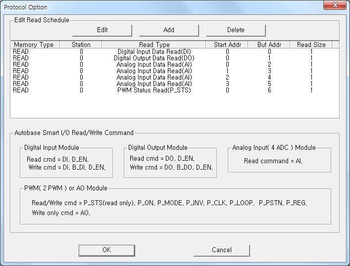 |
| <Figure 2> Example of Autobase Touch Smart I/O I communication driver’s Option dialogue box |
You can also set read schedule by using
![]() ,
,
![]() ,
,
![]() button and listbox of <Figure 2>.
button and listbox of <Figure 2>.
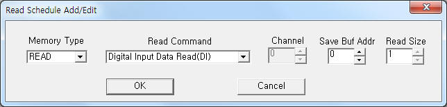 |
| <Figure 3> Example of Autobase Touch Smart I/O I communication driver’s read schedule Add/Edit dialogue box |
When you click Add button or Edit button in dialogue box of <Figure 2>, dialogue box of <Figure 3> will be shown.
You can set Smart I/O I module by using write settings.
Digital write
Digital write and analog write have the same setting parameters except output value(0 or 1).
Analog write
Analog write setting parameters are as follows:
1) PORT port no. (0 ~ 255)
2) STATION don't care.
3) ADDRESS writing bit number or channel number. ( refer to <Table 2> )
4) EXTRA 1 write command = DI, DO, AI, D_EN, P_STS, P_ON, P_MODE, P_INV, P_CLK, P_LOOP, P_PSTN, P_REG. ( refer to <Table 2> )
5) EXTRA 2 0 ~ 9 Data 3 setting value.
<Table 2> is write command and parameters of Autobase Touch Smart I/O I communication driver.
| Write command | Contents | Address |
Output value |
| DI | write of digitial input module | 0 ~ 7 bit position | 0 : Off, 1 : On |
| DO | write of digitial output module | ||
| B_DI | write of digitial input by byte unit | don't care | 0 ~ 255 ( each bit On, Off) |
| B_DO | write of digitial output by byte unit | ||
| D_EN | write of output enable for DI, DO | 0 = DI, 1 = DO |
0 ~ 255 example) 0 = all input, 255 = all output |
| P_ON | PWM Enable/Trig control | 0 = PWM A, 1 = PWM B |
0 : Off, 1 : On (run ) |
| P_MODE | PWM block mode setting | 1 = Phase mode, 2 = Register out mode, 4 = Register out mode 2, 9 = Phase mode 2 |
|
| P_INV | PWM output inverse setting | 0 = normal, 1 = inverse |
|
| P_CLK | PWM clock divide value setting | 0 = divide by 2, 1 = divide by 4, 2 = divide by 8, 3 = divide by 16 |
|
| P_LOOP | PWM step repetition value setting | 0 ~ 15 ( 0 = infinite ) |
|
| P_PSTN | PWM PSTN value setting | 0 ~ 3 = PSTN 1 ~ 4 of PWM A, 4 ~ 7 = PSTN 1 ~ 4 of PWM B |
word ( 0 ~ 65535 ) unit |
| P_REG | PWM out reg value setting | 0 ~ 3 = pattern value 1 ~ 4 of PWM A, 4 ~ 7 = pattern value 1 ~ 4 of PWM B |
double word unit |
| <Table 2> Write command and parameters of Autobase Touch Smart I/O I communication driver | |||
Write example 1)
PORT:0, station:0, ADDRESS:0000, Extra1:DO, Extra2 : 0, Output Value = 1
The setting parameter shown above is On control example for 1 st DO point of Autobase Touch Smart I/O Iequipment.
Write example 2)
PORT:0, station:0, ADDRESS:0007, Extra1:DO, Extra2 : 0, Output Value = 1
The setting parameter shown above is On control example for 8th DO point of Autobase Touch Smart I/O Iequipment.
Write example 3)
PORT:0, station:0, ADDRESS:0000, Extra1:P_ON, Extra2 : 0, Output Value = 1
The setting parameter shown above is Enable, Trig bit On setting example for PWM A channel.
Write example 4)
PORT:0, station:0, ADDRESS:0001, Extra1:P_MODE, Extra2 : 0, Output Value = 2
The setting parameter shown above is PWM mode setting example to Register out mode( output value = 2 ) for PWM B channel.
Write example 5)
PORT:0, station:0, ADDRESS:0003, Extra1:P_PSTN, Extra2 : 0
The setting parameter shown above is PSTN 4 output data pattern setting( word unit ) example for PWM A channel.
Write example 6)
PORT:0, station:0, ADDRESS:0005, Extra1:P_PSTN, Extra2 : 0
The setting parameter shown above is PSTN 2 output data pattern setting( word unit ) example for PWM B channel.
Write example 7)
PORT:0, station:0, ADDRESS:0007, Extra1:P_REG, Extra2 : 0
The setting parameter shown above is output data pattern 4 setting( double word unit ) example for PWM B channel.