AP-3604BA is the driver to communicate with Fire & Disaster prevention controller of Util Electronics in Korea.
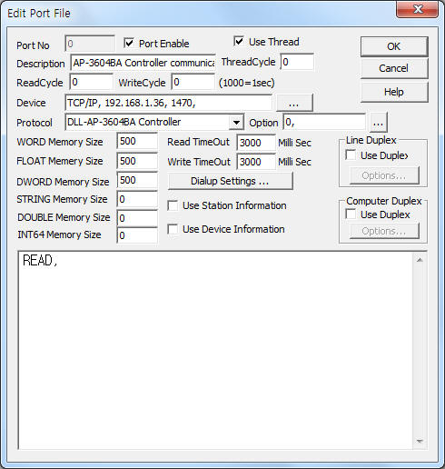
<Figure 1> is read setting example of AP-3604BA Controller communication driver.
|
|
| <Figure 1> Read setting example of AP-3604BA Controller communication driver |
Device part of <Figure 1> input Device Type(TCP/IP), IP address of controller(192.168.1.36), service port(1470), accordint to the setting of controller.
Also, you can set Readed data saving address(0 ~ 65535, default = 0) of EMR data and LED output data saving address(0 ~ 65535, default = 1) at option part.
Read schedule of AP-3604BA Controller communication driver
Read schedule of AP-3604BA Controller communication driver input 'READ' one line.
Read schedule example)
READ,
AP-3604BA Controller occurs 'EMR' data when pressing OK button' by user.
EMR data save '1' at EMR saving address of WORD memory.
After 3 ~ 4 seconds EMR data saving, communication driver clear the EMR saving value to '0'.
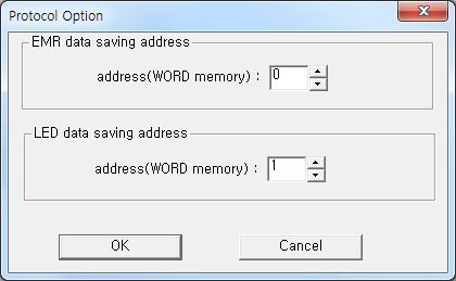
If you click the icon ![]() in protocol option part at
<Figure 1>, you
can see the dialog box such as <Figure 2>. you can also set Readed data
saving address of EMR data and LED output data saving address.
in protocol option part at
<Figure 1>, you
can see the dialog box such as <Figure 2>. you can also set Readed data
saving address of EMR data and LED output data saving address.
 |
|
<Figure 2> Example of AP-3604BA Controller communication driver’s Option dialog box |
You can set AP-3604BA Controller by using 'write settings'.
Digital Write
Digital write and analog write have the same setting parameters except output value.
Analog Write
Analog write setting parameters are as follows:
1) PORT Port no. (0 ~ 255)
2) STATION don't care.
3) ADDRESS don't care.
4) Extra1 write command = 1, 2, 3, 4, 5, C.
1 ~ 5 = LED 1 ~ LED 5 ON command,
C = all LED Off command.
5) Extra2 don't care.
After writing, save LED output data at 'LED output data saving address' such as <Table 1>.
| Write command | Saving value | Remarks |
| 1 | 1 ( bit 0 ON ) | save at LED output data saving address of WORD memory |
| 2 | 2 ( bit 1 ON ) | |
| 3 | 4 ( bit 2 ON ) | |
| 4 | 8 ( bit 3 ON ) | |
| 5 | 16 ( bit 4 ON ) | |
| C | 0 ( all bit clear ) | |
| <Table 1> Write command and LED output data saving value of AP-3604BA Controller communication driver | ||
Write example 1)
PORT : 0 STATION : 0 ADDRESS : 0000 EXTRA1 : 1 EXTRA2 : 0
The setting parameter shown above is LED 1 ON setting example for AP-3604BA Controller.
Write example 2)
PORT : 0 STATION : 0 ADDRESS : 0000 EXTRA1 : C EXTRA2 : 0
The setting parameter shown above is all LED OFF setting example for AP-3604BA Controller.
<Figure 3> shows the appearance of AP-3604BA Controller.
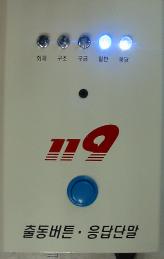 |
| <Figure 3> Appearance of AP-3604BA Controller |