AB-SLC Serial Communication Driver is the driver to communicate with AB SLC PLC of Rockwell Automation in U.S.A.
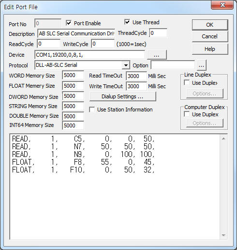
<Figure 1> is read setting example of AB-SLC Serial communication driver.
|
|
| <Figure 1> Read setting example of AB-SLC Serial communication driver |
Device part of <Figure 1> input Com Port(COM1), Baud Rate(19200), Parity Bit(0), Data Bit(8), Stop Bit(1) respectively.
Note) AB-SLC Serial CPU Type = 5/01, 5/02, 5/03, 5/04 …
Parity Bit, Data Bit, Stop Bit can set at AB SLC PLC Ladder program.
AB-SLC Serial communication driver’s read schedule
Read schedule setting parameters are as follows:
1) STATION – station = 0 ~ 255.
station no. of peer to peer connection = don't care.(0, or etc)
2) memory type(and file number) – memory type = O0, I1, S2, B3, T4, C5, R6, N7, F8, …
File Number 9 ~ 255 : B, T, C, R, N, F (setting by Ladder program)
3) Read Start Address – read start address of memory.
4) Save Start Address for Communication Server – save start address.
5) Read Size – word unit size.
T, C, N : 1 ~ 119 WORD,
F : 1 ~ 59 Float(double WORD).
Read schedule example)
READ, 1, C5, 0, 0, 50,
READ, 1, N7, 50, 50, 50,
READ, 1, N9, 0, 100, 100,
FLOAT, 1, F8, 55, 0, 45,
FLOAT, 1, F10, 0, 50, 32,
Note) O0, I1, S2, B3, T4, C5, R6, N7, F8 = default (fixed) memory type
<Table 1> is memory type and content of AB-SLC Serial communication driver.
| Memory(Device) Type | Content | Data Unit | Remarks |
| O0 | Output | WORD | |
| I1 | Input | read only | |
| S2 | System | ||
| B3 | Binary | Binary | |
| T4 | Timer | WORD | |
| C5 | Counter | ||
| R6 | Register | ||
| N7 | Integer | ||
| F8 | Float | FLOAT (4 Byte Data) | |
| 9 ~ 255 | User define | available memory type = B, T, C, R, N, F | setting by Ladder program |
| <Table 1> Memory type and content of AB-SLC Serial communication driver. | |||
If you click the icon ![]() in protocol
option part, you can see the dialogue box such as <Figure 2>. you can also set
read schedule by using this part.
in protocol
option part, you can see the dialogue box such as <Figure 2>. you can also set
read schedule by using this part.
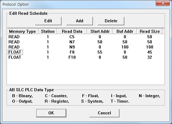 |
| <Figure 2> Example of AB-SLC Serial communication driver’s Option dialogue box |
You can set read schedule by using ![]() ,
, ![]() ,
, ![]() button
and listbox of <Figure 2>.
button
and listbox of <Figure 2>.
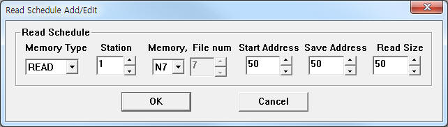 |
| <Figure 3> Example of AB-SLC Serial communication driver’s read schedule Add/Edit dialogue box |
When you click Add button or Edit button in dialogue box of <Figure 2>, dialogue box of <Figure 3> is shown.
You can write AB SLC PLC by writing settings.
Bit Write
Bit write setting parameters are as follows:
1) PORT : Port no. (0 ~ 255)
2) STATION : station = 0 ~ 255.
station no. of peer to peer connection = don't care.(0, or etc)
3) ADDRESS : Upper 3 digit = word unit writing address (10 digit), Lower 1 digit = 0 ~ F(16 digit) writing bit pos. (ex : 001A = 1 word A bit)
4) EXTRA 1 : memory type =O0, S2, B3, T4, C5, R6, N7, …
5) EXTRA 2 : R, T, C memory = 0 – status bit, 1 – setting value, 2 – count value,
Other memory = Don;t care.
Write example 1)
PORT : 0 STATION : 1 ADDRESS : 002F EXTRA1 : B3 EXTRA2 :
The setting parameter shown above is an example of bit write for 2 word, F bit of memory B3 for AB-SLC PLC connected with 0 port, 1 station.
Write example 2)
PORT : 0 STATION : 1 ADDRESS:0007 EXTRA1 : N7 EXTRA2 :
The setting parameter shown above is an example of bit write for 0 word, 7 bit of memory N7 for AB-SLC PLC connected with 0 port, 1 station.
Write example 3)
PORT : 0 STATION : 1 ADDRESS : 012A EXTRA1 : N9 EXTRA2 :
The setting parameter shown above is an example of bit write for 12 word, A bit of memory N9 for AB-SLC PLC connected with 0 port, 1 station.
Write example 4)
PORT:0 STATION:1 ADDRESS:0010 EXTRA1:T4 EXTRA2 : 0
The setting parameter shown above is an example of writing status bit for 1 word, 0 bit of memory T4 for AB-SLC PLC connected with 0 port, 1 station.
Write example 5)
PORT:0 STATION:1 ADDRESS:0010 EXTRA1:T4 EXTRA2 : 1
The setting parameter shown above is an example of setting value control for 1 word, 0 bit of memory T4 for AB-SLC PLC connected with 0 port, 1 station.
Write example 6)
PORT:0 STATION:1 ADDRESS:0010 EXTRA1:T4 EXTRA2 : 2
The setting parameter shown above is an example of count value control for 1 word, 0 bit of memory T4 for AB-SLC PLC connected with 0 port, 1 station.
Note) AB-SLC Serial communication driver don't support 'Bit Write' for 'F' memory.
Word Write
Word write setting parameters are as follows:
1) PORT : Port no. (0 ~ 255)
2) STATION : station = 0 ~ 255.
station no. of peer to peer connection = don't care.(0, or etc)
3) ADDRESS : word unit writing address (10 digit).
4) EXTRA 1 : memory type =O0, S2, B3, T4, C5, R6, N7, F8, …
5) EXTRA 2 : R, T, C memory = 0 – status bit, 1 – setting value, 2 – count value,
Other memory = Don;t care.
Write example 1)
PORT : 0 STATION : 1 ADDRESS : 0015 EXTRA1 : N7 EXTRA2 :
The setting parameter shown above is an example of word write for 15 word of memory N7 for AB-SLC PLC connected with 0 port, 1 station.
Write example 2)
PORT : 0 STATION : 1 ADDRESS : 0125 EXTRA1 : N9 EXTRA2 :
The setting parameter shown above is an example of word write for 125 word of memory N9 for AB-SLC PLC connected with 0 port, 1 station.
Write example 3)
PORT : 0 STATION : 1 ADDRESS : 0003 EXTRA1 : F8 EXTRA2 :
The setting parameter shown above is an example of word write for 3 float(double word) of memory F8 for AB-SLC PLC connected with 0 port, 1 station.
Write example 4)
PORT : 0 STATION : 1 ADDRESS : 0032 EXTRA1 : F10 EXTRA2 :
The setting parameter shown above is an example of word write for 32 float(double word) of memory F10 for AB-SLC PLC connected with 0 port, 1 station.
Write example 5)
PORT : 0 STATION : 1 ADDRESS : 0002 EXTRA1 : C5 EXTRA2 : 0
The setting parameter shown above is an example of writing status bit for 2 word of memory C5 for AB-SLC PLC connected with 0 port, 1 station.
Write example 6)
PORT : 0 STATION : 1 ADDRESS : 0002 EXTRA1 : C5 EXTRA2 : 1
The setting parameter shown above is an example of writing setting value for 2 word of memory C5 for AB-SLC PLC connected with 0 port, 1 station.
Write example 7)
PORT : 0 STATION : 1 ADDRESS : 0002 EXTRA1 : C5 EXTRA2 : 2
The setting parameter shown above is an example of writing count value for 2 word of memory C5 for AB-SLC PLC connected with 0 port, 1 station.
connection of RS-232C communication cable
RS-232C cable for serial communication use 'full cross RS-232C cable'. (Refer to <Figure 4>)
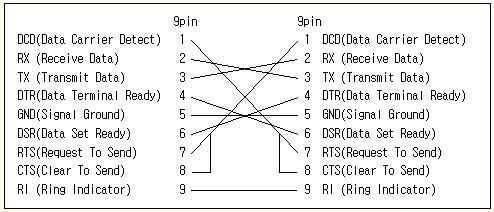 |
| <Figure 4> Connection of full cross RS-232C cable (9pin-9pin) |
Note) AB-SLC Serial communication have to use 'full RS-232C communication cable'.
connection of main power line
AB-SLC PLC's main power input AC22V or AC110V to power module. (Refer to<Figure 5> )
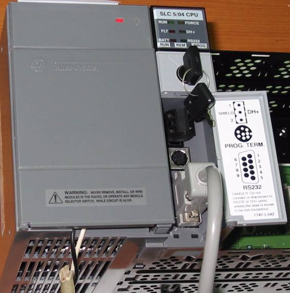 |
| <Figure 5> Appearance of AB-SLC PLC(connected main power line and communication cable) |